Chart 5.20
Chart 5.21
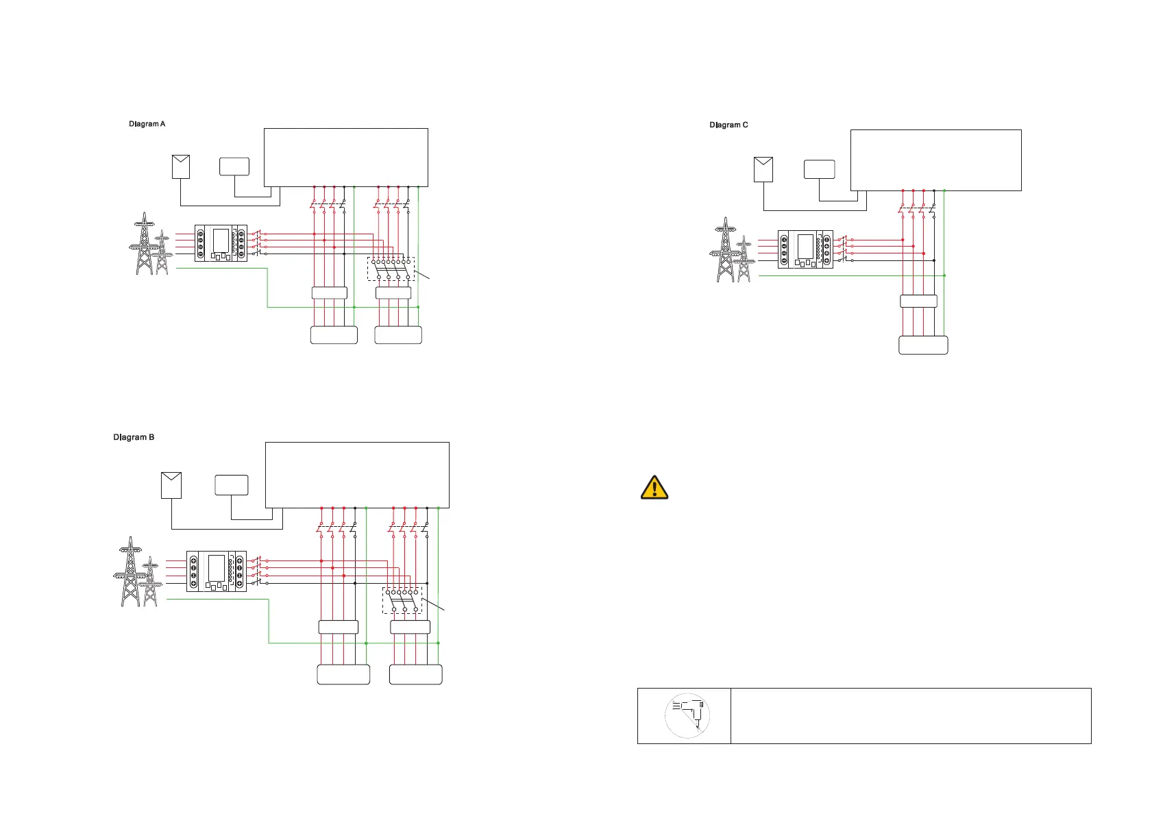
The recommended wiring diagram is as follows:
Note:
This diagram is an example for gird system without special requirement on electrical
wiring connection.
Note:
This diagram is an example for Australian and New Zealand gird system where neutral
line can't be switched.
SPHInverter
ACGRID
L3L2L1 L3
EPS OUTPUT
N N
E
L3
L1
N
N
E
E
ATS-T
Battery
PE
PV
Electic meter
L2L1
L3
L2
EPS Load
RCD
E
L1
L2
L3
N
L2L1
Load
RCD
SPHInverter
ACGRID
L3L2L1 L3
EPS OUTPUT
N N
E
L3
L1
N
N
E
E
ATS-T
Battery
PE
PV
Electic meter
L2L1
L3
L2
EPS Load
RCD
E
L1
L2
L3
N
L2L1
Load
RCD
Chart 5.22
Note:
This diagram is an example for customer who only wants to use the on grid storage
system.
Notice:
ØIf you want to use on gird only, please refer to chart 5.17 Connect with AC grid and
float EPS OUTPUT.
ØIf you have no battery now, you can also float BAT terminal, and this hybrid inverter
will only work like a PV inverter.
ØIf you want to use both on gird power and backup power, please refer to chart 5.15
and 5.16.Connect with AC grid and EPS OUTPUT like the chart show.
ØOn grid terminal and off grid terminal can't directly connect together.
ØOff Grid terminal can't connect to grid.
ØIf you want to use on gird and off grid, you can use ATS (automatic transfer switch)
like chart 5.15 and 5.16 before or ask Growatt for help to connect them.
ØThe first start of system needs Grid power.
SPHInverter
ACGRID
L3L2L1 N
L3 N E
Battery
PE
PV
Electic meter
E
L1
L2
L3
N
L2L1
Load
RCD
EPS output does not support half-wave load type devices,
such as hair dryers.
19
20

 Loading...