38
37
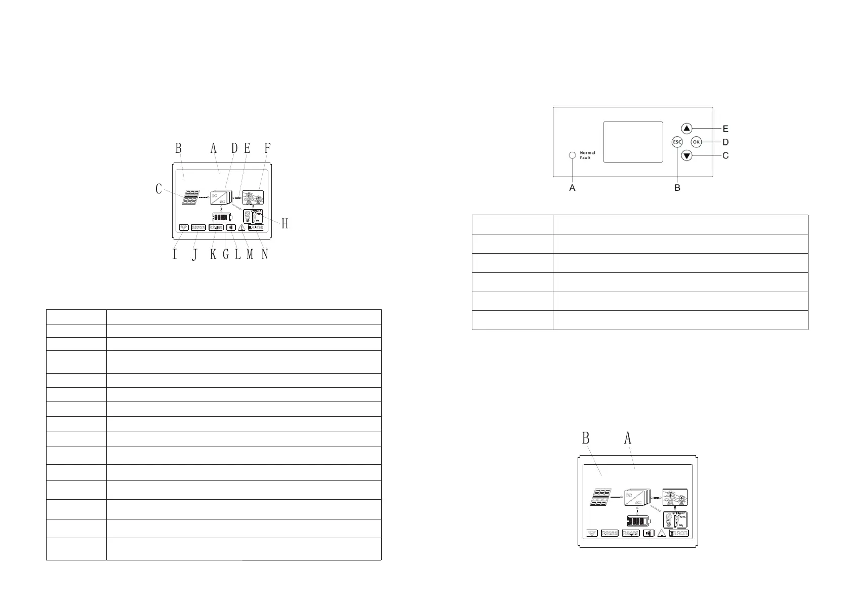
Location
Description
A
E
J
C
G
L
B
F
K
D
I
H
M
N
State
Information
PV input (if you connect two tracks, it will show two. Otherwise
show one)
SPH inverter
Power flow line
Grid
Battery (show the SOC in five grid, Every grid represents 20%)
Local load
Wireless communication
RS232
RS485
Buzzer(Reserved)
Warning
6.4 Display and button
6.4.1 LCD display area
Chart 6.2
Vb / Cb: 488.0 V 88%
Normal
Fault
Location
Description
A
B
D
C
E
Status
ESC- button(cancel control)
Down-button
Enter-button
UP-button
Notice:
LED showing status of SPH, it has two colors, one is green and another is red. Please turn
to 3.1 and read the detail of LED.
6.4.3 LCD display column
LCD display column is used to show the current state, basic information and fault
information. Also includes language setting, program charging/discharging priority and
system time. On default condition will take turns to display the information.
Chart 6.4
Chart 6.4
Chart 6.3
6.4.2 LED and button instruction
Vb / Cb: 488.0 V 88%
Normal

 Loading...