EasyManuals Logo

Growatt SPH Series Installation Manual

Growatt SPH Series
66 pages
To Next Page IconTo Next Page
To Previous Page IconTo Previous Page
Page #45 background imageLoading...
Page #45 background image
and set again.
The DIP switch is composed of six-digit binary number PINS. The different combination of the six PINS can
represent different inverter’s model, which is corresponding to the local grid standard. Each small white PIN
has two statuses, when set upward to “ON”, its value turns to “1”, when set downward, its value turns to “0”.
Concerning the matching of the PIN status and the country safety standard, please refer to the table below:
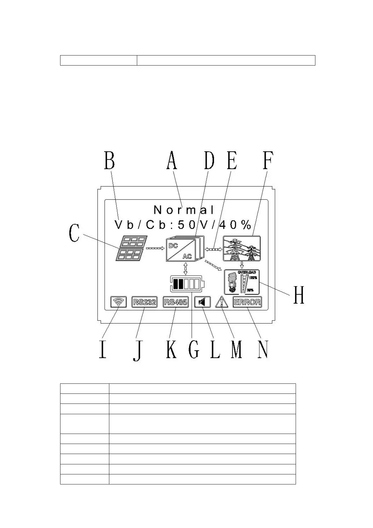
6.4 Display and button
6.4.1 LCD display area
Chart 6.2
Location Description
A State
B Information
C
PV input (If you connect two tracks, it will show two. Otherwise
show one)
D SPH inverter
E Power flow line
F Grid
G Battery (Show the SOC in five grid, Every grid represents 20%)
H Local load

Other manuals for Growatt SPH Series

Questions and Answers:

Question and Answer IconNeed help?

Do you have a question about the Growatt SPH Series and is the answer not in the manual?

Growatt SPH Series Specifications

General IconGeneral
TypeHybrid Inverter
Max. Input Voltage600V
Number of MPPTs2
Protection RatingIP65
Output Power Range3kW - 10kW
Rated AC Output Power3-10 kW
Communication InterfacesRS485, USB, Wi-Fi
Output Voltage230 V
Frequency50/60 Hz
Operating Temperature-25°C to 60°C
Cooling MethodNatural Convection

Related product manuals