English (GB)
7
5. EtherNet/IP, CIM 500 setup
5.1 Connecting the Ethernet cable
Use RJ45 plugs and an Ethernet cable. Connect the cable shield
to protective earth at both ends.
CIM 500 is designed for flexible network installation; the built-in
two-port switch makes it possible to daisy chain from product to
product without the need of additional Ethernet switches. The last
product in the chain is only connected to one of the Ethernet
ports. Each Ethernet port has its own MAC address.
Fig. 3 Example of an Industrial Ethernet network with CIM
500
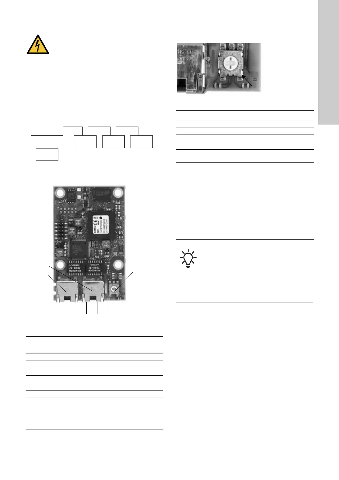
Fig. 4 CIM 500 Ethernet module
5.2 Selection of Industrial Ethernet protocol
The module has a rotary switch for selection of the Industrial
Ethernet protocol. See fig. 5.
Fig. 5 Selecting the Industrial Ethernet protocol
5.3 Setting the IP addresses
The CIM 500 Ethernet module is by default set to a fixed IP
address. It is possible to change the IP address settings from the
built-in webserver.
WARNING
Electric shock
Death or serious personal injury
- Connect CIM 500 only to SELV or SELV-E circuits.
TM05 6435 4711TM05 7431 1013
Pos. Description Designation
1 Industrial Ethernet RJ45 connector 1 ETH1
2 Industrial Ethernet RJ45 connector 2 ETH2
3 Rotary switch for protocol selection SW1
4 Data activity LED for connector 1 DATA1
5 Link LED for connector 1 LINK1
6 Data activity LED for connector 2 DATA2
7 Link LED for connector 2 LINK2
8
Green and red status LED for Ethernet
communication
LED1
9
Green and red status LED for internal
communication between module and
pump
LED2
Ethernet
switch
CIM 500
CIM 500
CIM 500
CIM 500
TM05 7481 1013
Pos. Description
0 PROFINET IO, default
1 Modbus TCP
2 BACnet IP
3 EtherNet/IP
4
GRM IP for Grundfos Remote Management, requires a
contract with Grundfos.
5 Grundfos iSOLUTIONS Cloud (GiC)
6...E
Reserved. LED1 is permanently red to indicate an
invalid configuration.
F
Resetting to factory settings.
1. Set the rotary switch to this position
2. LED1 starts to flash red and green for 20 seconds to
indicate that factory resetting is about to take place.
3. After 20 seconds, LED1 stops to flash and factory
resetting is initiated.
4. When both LED1 and LED2 switch off, the resetting
is completed. The rotary switch can be moved to
another position.
If the rotary switch position is changed when the
module is powered on, the module will restart and
use the protocol associated with the new position.
Default IP settings
used by the
webserver
IP address: 192.168.1.100
Subnet mask: 255.255.255.0
Gateway: 192.168.1.1
IP settings for
EtherNet/IP
Make the settings via the webserver

 Loading...


