English (US)
10
6.6 Bus connection cable
6.6.1 New installations
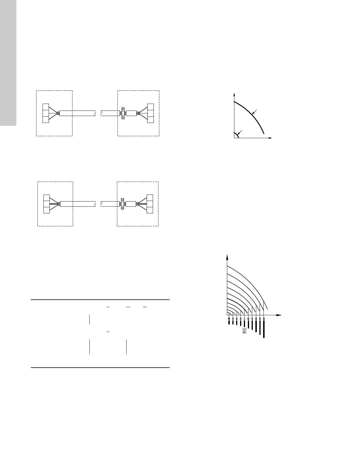
For the bus connection, use a screened 3-core cable with a
conductor cross-section of 28-16 AWG.
• If the pump is connected to a unit with a cable clamp which is
identical to the one on the pump, connect the screen to this
cable clamp.
• If the unit has no cable clamp as shown in fig. 14, leave the
screen unconnected at this end.
Fig. 14 Connection with screened 3-core cable
6.6.2 Replacing an existing pump
• If a screened 2-core cable is used in the existing installation,
connect it as shown in fig. 15.
Fig. 15 Connection with screened 2-core cable
• If a screened 3-core cable is used in the existing installation,
follow the instructions in section 6.6.1 New installations on
page 10.
7. Modes
Grundfos E-pumps are set and controlled according to operating
and control modes.
7.1 Overview of modes
1) For this control mode the pump is equipped with a pressure
sensor. The pump may also be equipped with a temperature
sensor in which case the description would be constant
temperature in control mode controlled.
7.2 Operating mode
When the operating mode is set to Normal, the control mode can
be set to controlled or uncontrolled. See section 7.3 Control mode
on page 10.
The other operating modes that can be selected are Stop, Min. or
Max.
• Stop: the pump has been stopped
• Min.: the pump is operating at its minimum speed
• Max.: the pump is operating at its maximum speed.
Figure 16 is a schematic illustration of min. and max. curves.
Fig. 16 Min. and max. curves
The max. curve can for instance be used in connection with the
venting procedure during installation.
The min. curve can be used in periods in which a minimum flow is
required.
If the power supply to the pump is disconnected, the mode setting
will be stored.
The remote control R100 offers additional possibilities of setting
and status displays. See section 10. Setting by means of R100 on
page 12.
7.3 Control mode
7.3.1 Pumps without factory-fitted sensor
The pumps are factory-set to control mode uncontrolled.
In control mode uncontrolled, the pump will operate according to
the constant curve set, fig. 17.
Fig. 17 Pump in control mode uncontrolled (constant curve)
TM02 8841 0904TM02 8842 0904
Operating modes Normal Stop Min. Max.
Control modes Uncontrolled Controlled
Constant
curve
Constant
pressure
1)
TM00 5547 0995TM00 7746 1304

 Loading...


