English (US)
6
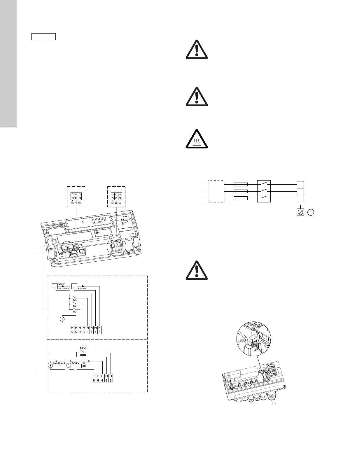
6.2.9 Connections
As a precaution, the wires to be connected to the following
connection groups must be separated from each other by
reinforced insulation in their entire lengths:
Group 1: Inputs
• start/stop terminals 2 and 3
• digital input terminals 1 and 9
• setpoint input terminals 4, 5 and 6
• sensor input terminals 7 and 8
• GENIbus terminals B, Y and A
All inputs (group 1) are internally separated from the power-
conducting parts by reinforced insulation and galvanically
separated from other circuits.
All control terminals are supplied with protective extra-low voltage
(PELV), thus ensuring protection against electric shock.
Group 2: Output (relay signal, terminals NC, C, NO)
The output (group 2) is galvanically separated from other circuits.
Therefore, the supply voltage or protective extra-low voltage can
be connected to the output as desired.
6.2.10 Three-phase pumps, 1.5 - 10 hp
Group 3: Power supply (terminals L1, L2, L3)
Fig. 5 Connection terminals
A galvanic separation must fulfill the requirements for reinforced
insulation including creepage distances and clearances specified
in EN 60335.
6.3 Three-phase pumps, 15-30 hp
6.3.1 Preparation
Before connecting the E-pump to the power supply, take the
issues illustrated in the figure below into consideration.
Fig. 6 Power supply-connected pump with power switch,
backup fuses, additional protection and protective
grounding
6.3.2 Protection against electric shock - indirect contact
EN 61800-5-1 specifies that the pump must be stationary and
installed permanently when the leakage current is > 10 mA.
One of the following requirements must be fulfilled:
• A single protective ground lead (7 AWG minimum copper)
Fig. 7 Connection of a single protective ground lead using
one of the leads of a 4-core power cable
(7 AWG minimum)
If no external on/off switch is connected,
connect terminals 2 and 3 using a short wire.
TM05 2985 0812
6: GND (frame)
5: +10 V
4: Setpoint input
3: GND (frame)
2: Start/stop
Group 1
Group 2
Group 3
13: GND (frame)
12: Analog output
11: Digital input 4
10: Digital input 3
1: Digital input 2
9: GND (frame)
8: +24 V
7: Sensor input
B: RS-485B
Y: Screen
A: RS-485A
Warning
The user or the installer is responsible for the
installation of correct grounding and protection
according to current national and local
standards. All operations must be carried out by
qualified personnel.
Warning
Never make any connections in the pump
terminal box unless all electric supply circuits
have been switched off for at least 5 minutes.
Note for instance that the signal relay may be
connected to an external supply which is still
connected when the power supply is
disconnected.
Warning
The surface of the terminal box may be above
158 °F (70 °C) when the pump is operating.
TM00 9270 4696
Warning
The pump must be grounded in accordance with
national regulations.
As the leakage current of 15-30 hp motors is
> 10 mA, take extra precautions when grounding
these motors.
TM04 3021 3508

 Loading...


