English (US)
12
9.1 Setting of operating mode
Settings available:
•Normal
•Stop
•Min.
•Max.
Start/stop of pump
Start the pump by continuously pressing until the desired
setpoint is indicated. This is operating mode Normal.
Stop the pump by continuously pressing until none of the light
fields are activated and the green indicator light flashes.
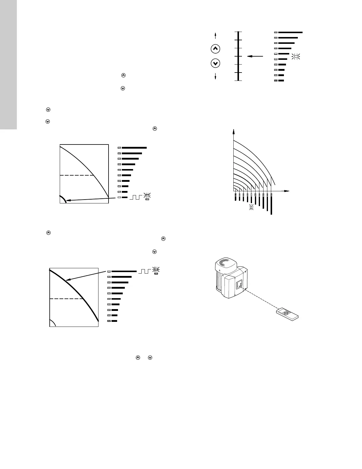
Setting to Min.
Press
continuously to change to the min. curve of the pump
(bottom light field flashes). When the bottom light field is on,
press for 3 seconds until the light field starts flashing.
To return to uncontrolled or controlled operation, press
continuously until the desired setpoint is indicated.
Fig. 21 Min. curve duty
Setting to Max.
Press continuously to change to the max. curve of the pump
(top light field flashes). When the top light field is on, press for
3 seconds until the light field starts flashing.
To return to uncontrolled or controlled operation, press
continuously until the desired setpoint is indicated.
Fig. 22 Max. curve duty
9.2 Setpoint setting
Set the desired setpoint by pressing the button or .
The light fields on the control panel will indicate the setpoint set.
See examples in sections 9.2.1 on page 12 and 9.2.2 on page 12.
9.2.1 Pump in control mode controlled (pressure control)
Example
Figure 23 shows that the light fields 5 and 6 are activated,
indicating a desired setpoint of 3 bar. The setting range is equal
to the sensor measuring range (see sensor nameplate).
Fig. 23 Setpoint set to 3 bar, pressure control
9.2.2 Pump in control mode uncontrolled
Example
In control mode uncontrolled, the pump performance is set within
the range from min. to max. curve. See fig. 24.
Fig. 24 Pump performance setting, control mode uncontrolled
10. Setting by means of R100
The pump is designed for wireless communication with
Grundfos remote control R100.
Fig. 25 R100 communicating with the pump via infra-red light
During communication, the R100 must be pointed at the control
panel. When the R100 communicates with the pump, the red
indicator light will flash rapidly. Keep pointing the R100 at the
control panel until the red LED diode stops flashing.
The R100 offers setting and status displays for the pump.
The displays are divided into four parallel menus (see fig. 34):
0. GENERAL (see operating instructions for the R100)
1. OPERATION
2. STATUS
3. INSTALLATION
The figure above each individual display in fig. 34 refers to the
section in which the display is described.
TM00 7346 1304TM00 7345 1304
TM00 7743 0904TM00 7746 1304TM02 0936 0501

 Loading...


