9
English (US)
6.4 Signal cables
• Use screened cables with a conductor cross-section of min.
28 AWG and max. 16 AWG for external on/off switch, digital
input, setpoint and sensor signals.
• Connect the screens of the cables to frame at both ends with
good frame connection. The screens must be as close as
possible to the terminals. See fig. 11.
Fig. 11 Stripped cable with screen and wire connection
• Always tighten screws for frame connections whether a cable
is fitted or not.
• Make the wires in the pump terminal box as short as possible.
6.5 E-pump electrical connections
6.5.1 Connection of E-pump to Danfoss pressure sensor
MBS3000
The blue wire of the pressure sensor is connected to the #7
terminal of the E-pump. The brown wire of the pressure sensor is
connected to the #8 terminal of the E-pump.
See section 6.4 Signal cables on page 9 for additional details.
Fig. 12 Danfoss pressure sensor
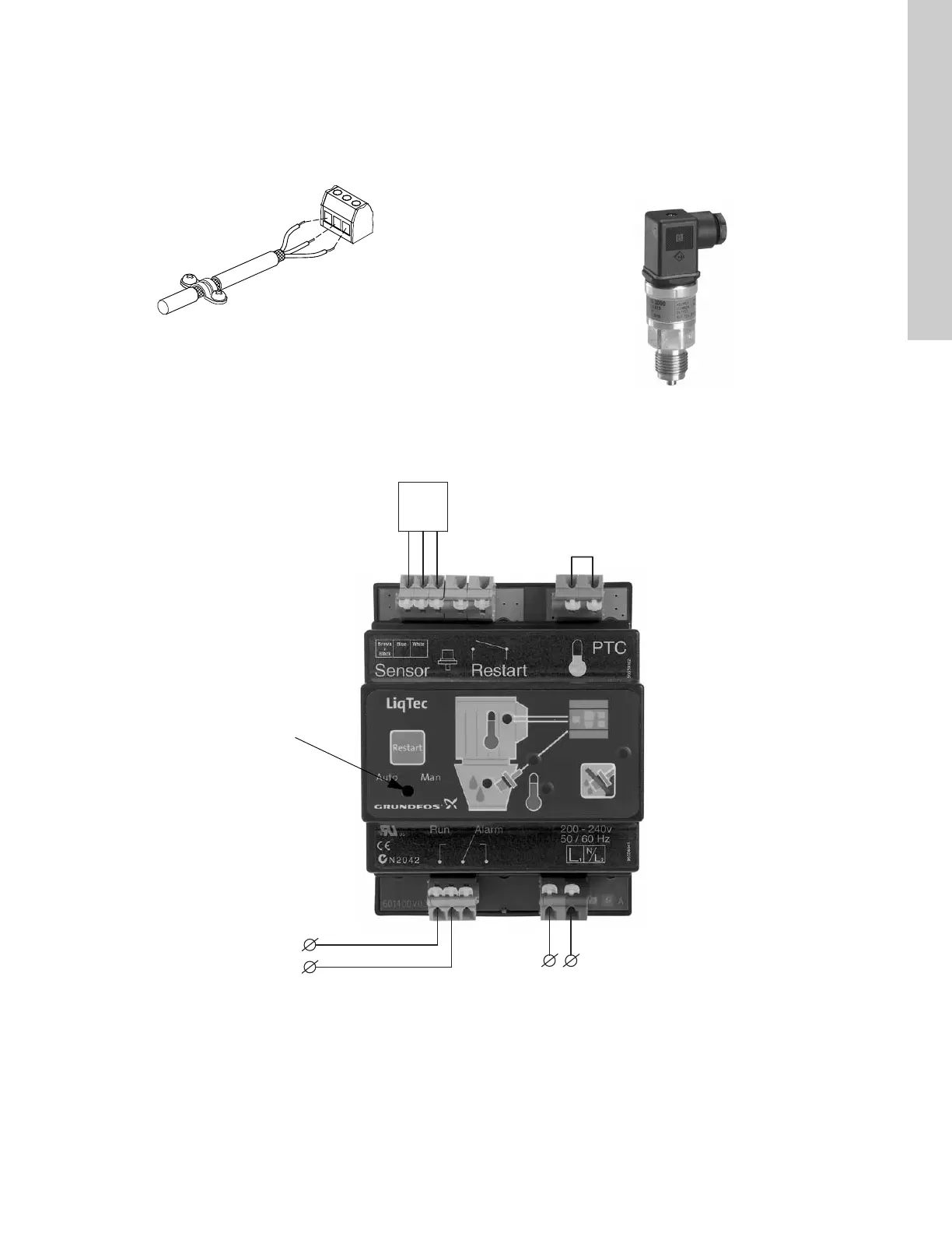
6.5.2 Connection of E-pump to LiqTec®
Fig. 13 Connection of E-pump to LiqTec
TM02 1325 0901
TM05 1533 2911
TM03 0437 5104
Dry-running sensor
Set to automatic resetting
Connection terminals on E-pump:
2 (Start/Stop) and 3 (GND)
3
2
1 x 200-240 VAC
or
1 X 80-130 VAC
Brown
Black
Blue
White
Jumper cable

 Loading...


