English (US)
8
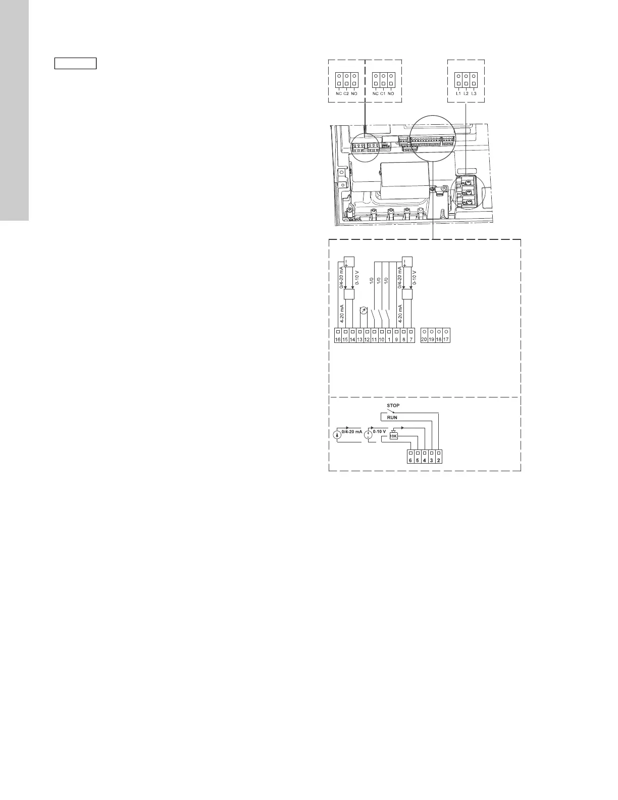
6.3.9 Connections
As a precaution, the wires to be connected to the following
connection groups must be separated from each other by
reinforced insulation in their entire lengths:
Group 1: Inputs
• start/stop terminals 2 and 3
• digital input terminals 1 and 9
• setpoint input terminals 4, 5 and 6
• sensor input terminals 7 and 8
• GENIbus terminals B, Y and A
All inputs (group 1) are internally separated from the power-
conducting parts by reinforced insulation and galvanically
separated from other circuits.
All control terminals are supplied with protective extra-low voltage
(PELV), thus ensuring protection against electric shock.
Group 2: Output (relay signal, terminals NC, C, NO)
The output (group 2) is galvanically separated from other circuits.
Therefore, the supply voltage or protective extra-low voltage can
be connected to the output as desired.
Group 3: Power supply (terminals L1, L2, L3)
Fig. 10 Connection terminals
A galvanic separation must fulfill the requirements for reinforced
insulation including creepage distances and clearances specified
in EN 61800-5-1.
If no external on/off switch is connected, connect
terminals 2 and 3 using a short wire.
TM05 2986 0812
6: GND (frame)
5: +10 V
4: Setpoint input
3: GND (frame)
2: Start/stop
Group 2
Group 3
20: PT 100 B
19: PT 100 B
18: PT 100 A
17: PT 100 A
16: GND (frame)
15: +24 V
14: Sensor input 2
13: GND
12: Analog output
11: Digital input 4
10: Digital input 3
1: Digital input 2
9: GND (frame)
8: +24 V
7: Sensor input
B: RS-485B
Y: Screen
A: RS-485A
Group 1

 Loading...


