7
English (US)
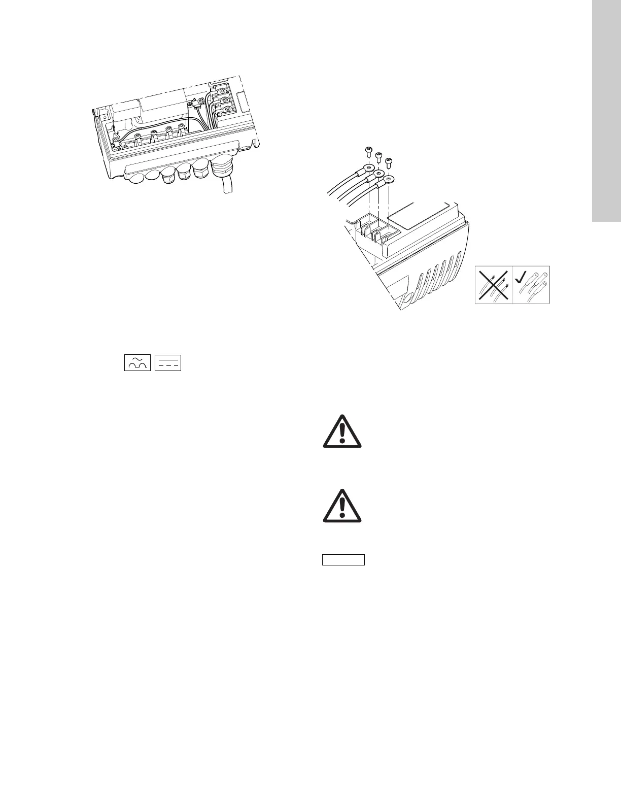
• Two protective ground leads of the same cross-sectional area
as the power supply leads, with one lead connected to an
additional ground terminal in the terminal box.
Fig. 8 Connection of two protective ground leads using two of
the leads of a 5-core power supply cable
Protective ground leads must always have a yellow/green (PE) or
yellow/green/blue (PEN) color marking.
6.3.3 Backup fuses
For recommended fuse sizes, see section 22.1 Supply voltage on
page 32.
6.3.4 Additional protection
If the pump is connected to an electric installation where an
ground leakage circuit breaker (ELCB) is used as additional
protection, the circuit breaker must be of a type marked with the
following symbols:
This circuit breaker is type B.
The total leakage current of all the electrical equipment in the
installation must be taken into account.
The leakage current of the motor in normal operation can be seen
in section 22.3 Leakage current.
During start and at asymmetrical supply systems, the leakage
current can be higher than normal and may cause the ELCB to
trip.
6.3.5 Motor protection
The pump requires no external motor protection. The motor
incorporates thermal protection against slow overloading and
blocking (IEC 34-11, TP 211).
6.3.6 Protection against voltage transients
The pump is protected against voltage transients in accordance
with EN 61800-3 and is capable of withstanding a VDE 0160
pulse.
The pump has a replaceable varistor which is part of the transient
protection.
Over time this varistor will be worn and need to be replaced.
When the time for replacement has come, R100 and PC Tool
E-products will indicate this as a warning. See section
20. Maintenance and service on page 31.
6.3.7 Supply voltage
3 x 460-480 V - 10 %/+ 10 %, 50/60 Hz, PE.
The supply voltage and frequency are marked on the pump
nameplate. Make sure that the motor is suitable for the power
supply of the installation site.
The wires in the terminal box must be as short as possible.
Excepted from this is the protective ground lead which must be so
long that it is the last one to be disconnected in case the cable is
inadvertently pulled out of the cable entry.
Fig. 9 Power connection
Cable glands
Cable glands comply with EN 50626.
• 1 x M40 cable gland
• 1 x M20 cable gland
• 2 x M16 cable gland
• 2 x M16 knock-out cable entries.
Grid types
Three-phase E-pumps can be connected to all grid types.
6.3.8 Start/stop of pump
When the pump is switched on via the power supply, it will start
after approx. 5 seconds.
If a higher number of starts and stops is desired, use the input for
external start/stop when starting/stopping the pump.
When the pump is switched on via an external on/off switch, it will
start immediately.
TM03 8606 2007
TM03 8605 2007 - TM04 3048 3508
Warning
If the supply cable is damaged, it must be
replaced by qualified personnel.
Warning
Do not connect three-phase E-pumps to a power
supply with a voltage between phase and ground
of more than 440 V.
The number of starts and stops via the power
supply must not exceed 4 times per hour.
Torques, terminals L1-L3:
Min. torque: 1.6 ft-lbs
Max. torque: 1.8 ft-lbs

 Loading...


