English (US)
18
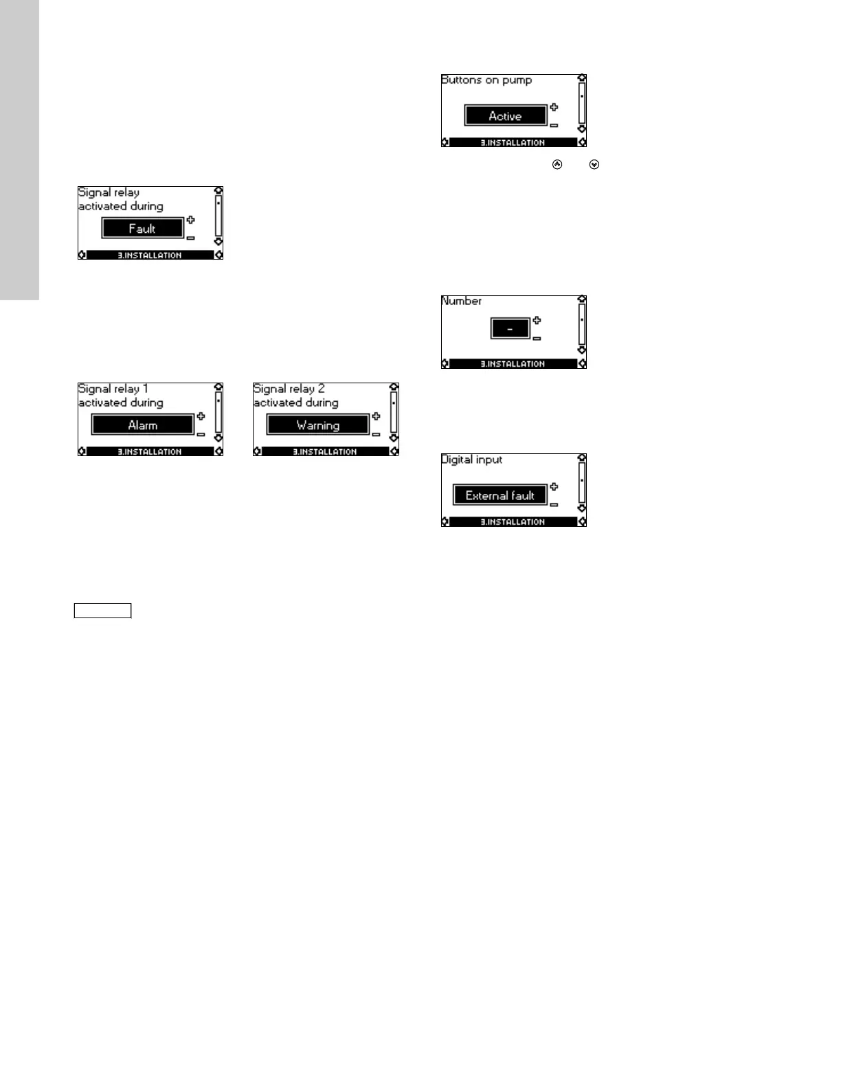
10.3.4 Signal relay
Pumps of 1.5 - 10 hp have one signal relay. The factory setting of
the relay will be Fault.
Pumps of 15-30 hp have two signal relays. Signal relay 1 is
factory set to Alarm and signal relay 2 to Warning.
In one of the displays below, select in which one of three or six
operating situations the signal relay should be activated.
For further information, see section 17. Indicator lights and signal
relay on page 28.
10.3.5 Buttons on pump
The operating buttons and on the control panel can be set
to these values:
•Active
• Not active.
When set to Not active (locked), the buttons do not function. Set
the buttons to Not active if the pump should be controlled via an
external control system.
10.3.6 Pump number
A number between 1 and 64 can be allocated to the pump. In the
case of bus communication, a number must be allocated to each
pump.
10.3.7 Digital inputs
The digital inputs of the pump can be set to different functions.
Select one of the following functions:
• Min. (min. curve)
• Max. (max. curve)
• External fault
• Flow switch
• Dry running (from external sensor) (only three-phase pumps).
The selected function is activated by closing the contact between
terminals 1 and 9, 1 and 10 or 1 and 11.
See also section 13.2 Digital input on page 27.
Min.:
When the input is activated, the pump will operate according to
the min. curve.
Max.:
When the input is activated, the pump will operate according to
the max. curve.
External fault:
When the input is activated, a timer will be started. If the input is
activated for more than 5 seconds, the pump will be stopped and
a fault will be indicated. If the input is deactivated for more than 5
seconds, the fault condition will cease and the pump can only be
restarted manually by resetting the fault indication.
Flow switch:
When this function is selected, the pump will be stopped when a
connected flow switch detects low flow.
It is only possible to use this function if the pump is connected to
a pressure sensor.
If the input is activated for more than 5 seconds, the stop function
incorporated in the pump will take over. See section 10.3.8 Stop
function on page 19.
1.5 - 10 hp
• Ready
• Fault
• Operation
• Pump running (only three-phase pumps, 1.5 - 10 hp)
• Warning (only three-phase pumps, 1-10 hp).
15-30 hp 15-30 hp
• Ready
•Alarm
• Operation
• Pump running
• Warning
• Relubricate.
• Ready
•Alarm
• Operation
• Pump running
• Warning
• Relubricate.
Fault and Alarm cover faults resulting in Alarm.
Warning covers faults resulting in Warning.
Relubricate covers only that one individual event.
For distinction between alarm and warning, see
section 10.1.3 Fault indications on page 14.

 Loading...


