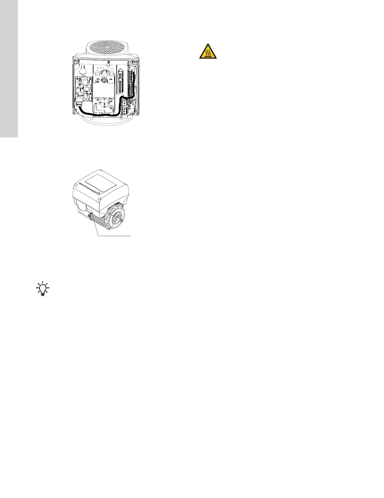
8. Route the wires for the CIM module. See the example in the
figure below.
TM064085
Example of wire routing
9. Fit the CIM cover.
10. If the CIM module is supplied with an FCC label, then place this
on the terminal box. See the figure below.
TM057028
FCC label
11. Fit the terminal box cover (figure Removing the terminal box
cover above, B) and cross-tighten the four mounting screws (A)
to 6 Nm.
Make sure that the terminal box cover is aligned with
the operating panel. See the section on changing the
position of the operating panel.
Related information
5.8 Changing the position of the control (operating) panel
7. User interfaces
WARNING
Hot surface
Death or serious personal injury
‐ Only touch the buttons on the display as the product
may be very hot.
You can make the pump settings by means of the following user
interfaces:
Operating panels
• Standard operating panel. See the section on the
standard operating panel.
• Advanced operating panel. See the section on the
advanced operating panel.
Remote controls
• Grundfos GO Remote. See the section on Grundfos
GO Remote.
• Grundfos R100 remote control. See the section on R100 remote
control.
If the power supply to the pump is switched off, the settings are
stored.
Related information
7.1 Standard operating panel
7.2 Advanced operating panel
7.3 Grundfos GO Remote
7.4 R100 remote control
20
English (US)

 Loading...


