Terminal Type Function
Y GENIbus, Y GENIbus, GND
B GENIbus, B GENIbus, B (-)
3 GND Ground
15 +24 V Supply
8 +24 V Supply
26 +5 V
Supply to potentiometer and
sensor
23 GND Ground
25 GDS TX
Grundfos Digital Sensor
output
24 GDS RX Grundfos Digital Sensor input
7 AI2
Analog input:
0-20 mA / 4-20 mA
0.5 - 3.5 V / 0-5 V / 0-10 V
Related information
11.6 Other technical data
6.6 Signal cables
• Use screened cables with a cross-sectional area of minimum 28
AWG and maximum 16 AWG for the external on/off switch,
digital inputs and setpoint signals.
• Connect the screens of the cables to the frame at both ends
with good connection. The screens must be as close as
possible to the terminals. See the figure below.
TM021325
Stripped cable with screen and wire connections
• Always tighten screws for frame connections whether a cable is
fitted or not.
• The wires in the motor terminal box must be as short as
possible.
Connection of Danfoss pressure sensor MBS3000 to E-pump
TM051533_2911
MBS3000 pressure sensor
Use screened cables with a cross-sectional area of minimum 28
AWG and maximum 16 AWG.
The blue wire of the pressure sensor is connected to the #4
terminal of the E-pump. The brown wire of the pressure sensor is
connected to the #8 terminal of the E-pump.
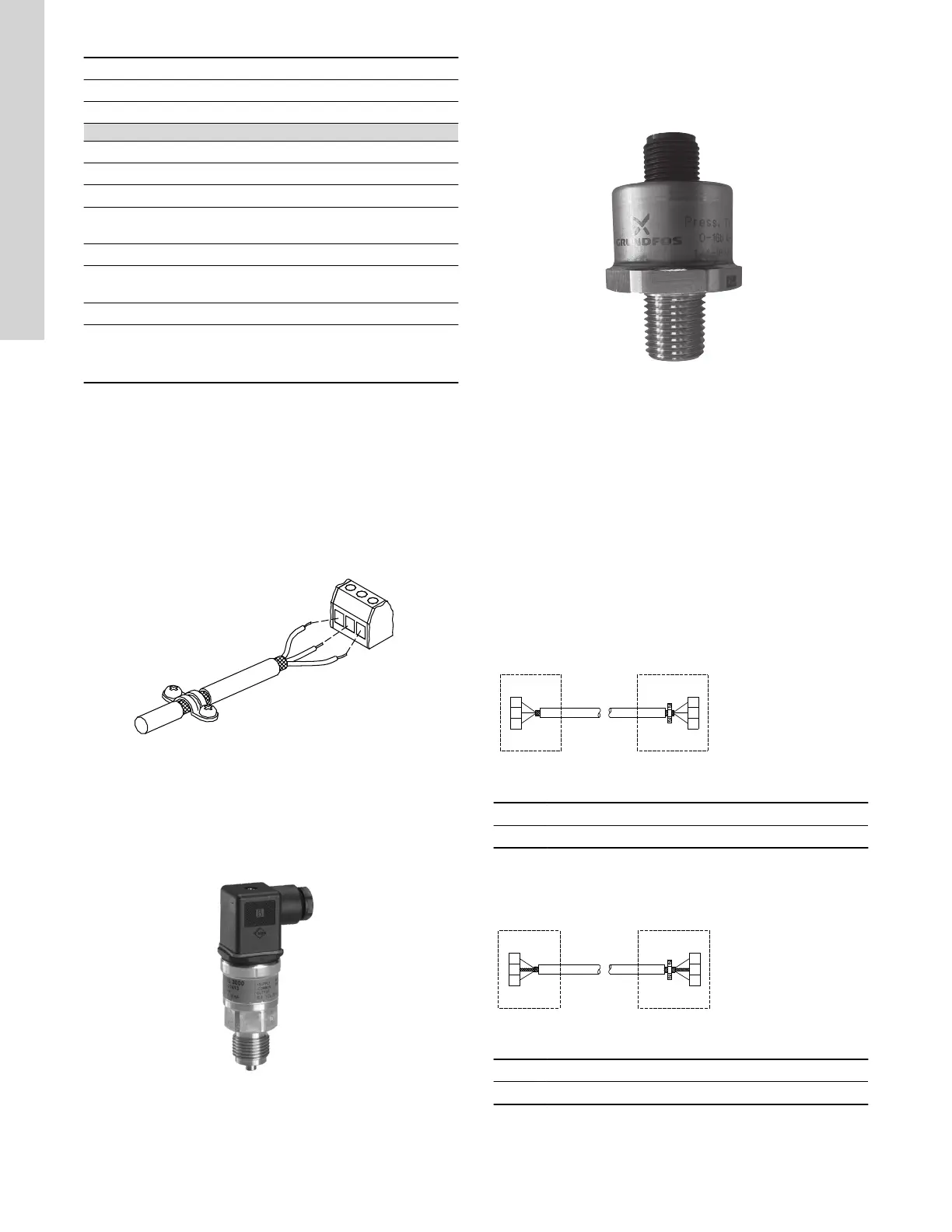
Connection of Grundfos pressure sensor ISP44 to E-pump
TM083396
ISP44 pressure sensor
Use unscreened cables with a cross-sectional area of minimum 28
AWG and maximum 16 AWG.
The blue wire of the pressure sensor is connected to the #4
terminal of the E-pump. The brown wire of the pressure sensor is
connected to the #8 terminal of the E-pump.
6.7 Bus connection cable
New installations
For the bus connection, use a screened 3-core cable with a cross-
sectional area of minimum 28 AWG and maximum 16 AWG.
If the motor is connected to a unit with a cable clamp which is
identical to the one on the motor, connect the screen to this cable
clamp.
If the unit has no cable clamp leave the screen unconnected at this
end. See the figure below.
TM053973
Connection with screened 3-core cable
Pos. Description
1 Motor
Replacing a motor
• If a 2-core cable is used in the installation, connect it as shown
in the figure below.
TM054035
Connection with screened 2-core cable
Pos. Description
1 Motor
• If a screened 3-core cable is used in the installation, follow the
instructions in the section on the new installations above.
18
English (US)

 Loading...


