13
English (US)
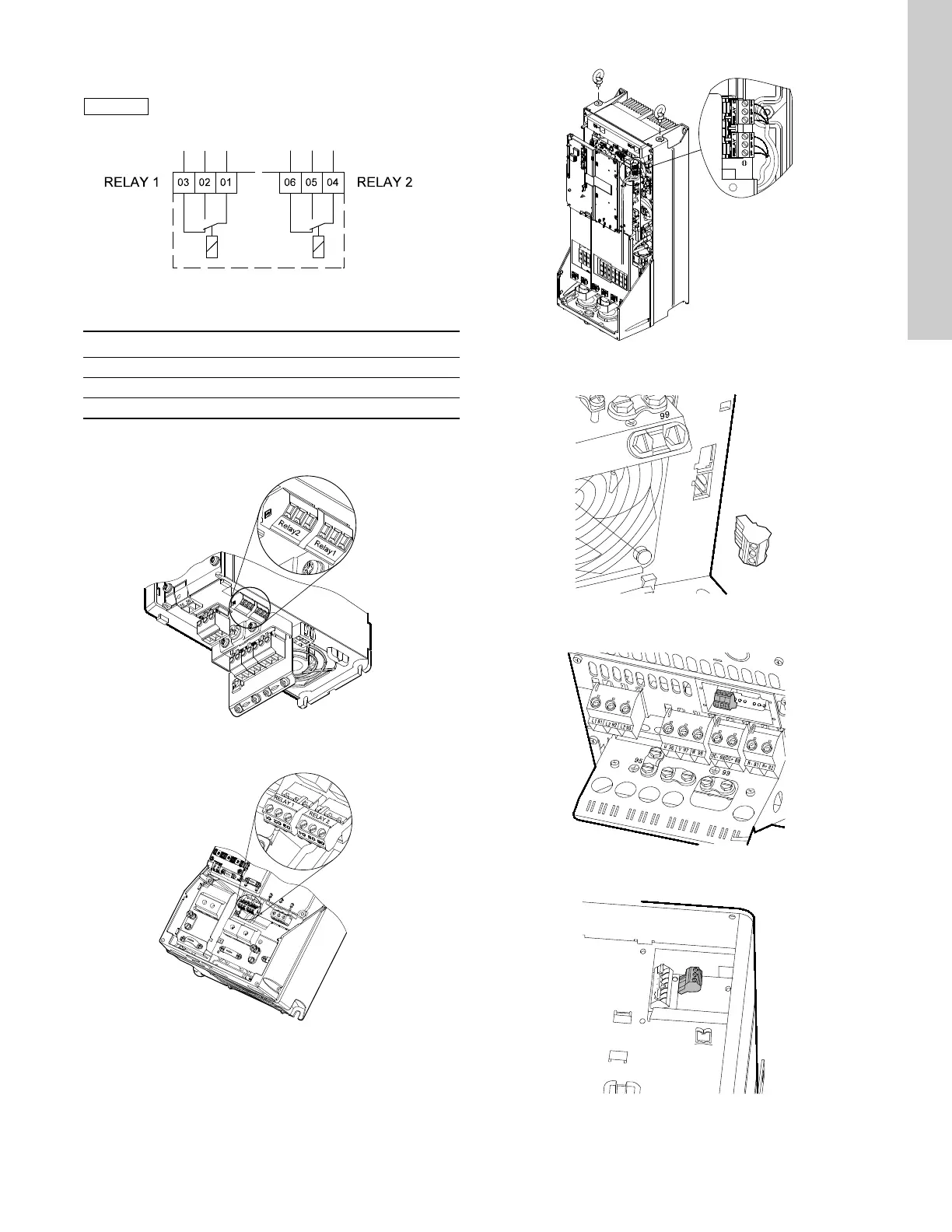
7.4 Connecting the signal relays
Fig. 29 Terminals for signal relays in normal state
(not activated)
Access to signal relays
The relay outputs are positioned as shown in figs 30 to 35.
Fig. 30 Terminals for relay connection, A2 and A3
Fig. 31 Terminals for relay connection, A4, A5, B1 and B2
Fig. 32 Terminals for relay connection, C1 and C2
Fig. 33 Terminals for relay connection, B3
Fig. 34 Terminals for relay connection, B4
Fig. 35 Terminals for relay connection, C3 and C4, in the
upper right corner of the CUE
As a precaution, signal cables must be separated
from other groups by reinforced insulation in
their entire lengths.
TM03 8801 2507
Terminal Function
C 1C 2Common
NO 1 NO 2 Normally open contact
NC 1 NC 2 Normally closed contact
TM03 9007 2807TM03 9008 2807
TM03 9009 2807TM03 9442 4007TM03 9441 4007TM03 9440 4007