English (US)
28
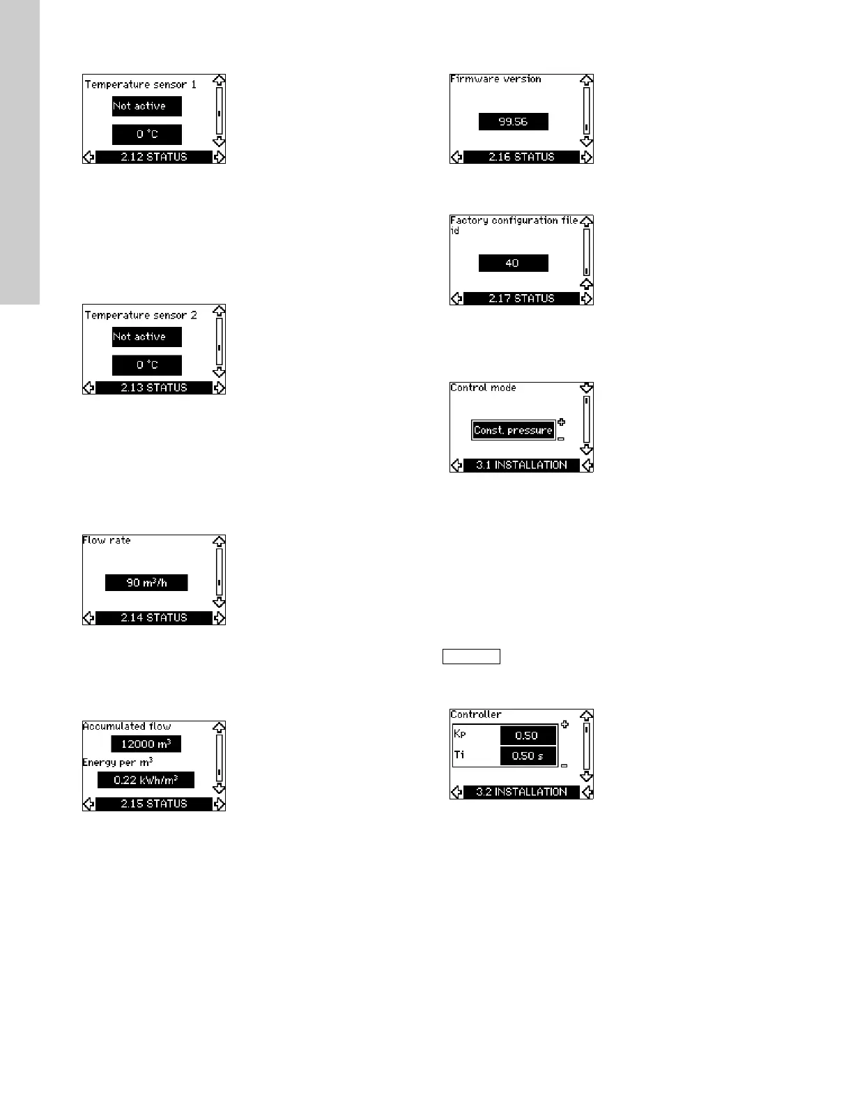
11.6.12 Temperature sensor 1 (2.12)
This display is only shown if an MCB 114 sensor input module
has been installed.
The display shows the measuring point and the actual value
measured by a Pt100/Pt1000 temperature sensor 1 connected to
the MCB 114. The measuring point is selected in display 3.21.
If no sensor is connected to the CUE, "-" will appear in the
display.
11.6.13 Temperature sensor 2 (2.13)
This display is only shown if an MCB 114 sensor input module
has been installed.
The display shows the measuring point and the actual value
measured by a Pt100/Pt1000 temperature sensor 2 connected to
the MCB 114. The measuring point is selected in display 3.22.
If no sensor is connected to the CUE, "-" will appear in the
display.
11.6.14 Flow rate (2.14)
This display is only shown if a flowmeter has been configured.
The display shows the actual value measured by a flowmeter
connected to the digital pulse input (terminal 33) or the analog
input (terminal 54).
11.6.15 Accumulated flow (2.15)
This display is only shown if a flowmeter has been configured.
The display shows the value of the accumulated flow and the
specific energy for the transfer of the pumped liquid.
The flow measurement can be connected to the digital pulse input
(terminal 33) or the analog input (terminal 54).
11.6.16 Firmware version (2.16)
This display shows the version of the software.
11.6.17 Configuration file (2.17)
This display shows the configuration file.
11.7 Menu INSTALLATION
11.7.1 Control mode (3.1)
Select one of the following control modes:
• Open loop
• Constant pressure
• Constant differential pressure
• Proportional differential pressure
• Constant flow rate
• Constant temperature
• Constant level
• Constant other value.
11.7.2 Controller (3.2)
The CUE has a factory setting of gain (K
p
) and integral time (T
i
).
However, if the factory setting is not the optimum setting, the gain
and the integral time can be changed in the display.
• The gain (K
p
) can be set within the range from 0.1 to 20.
• The integral time (Ti) can be set within the range from 0.1 to
3600 s. If 3600 s is selected, the controller will function as a P
controller.
• Furthermore, it is possible to set the controller to inverse
control, meaning that if the setpoint is increased, the speed
will be reduced. In the case of inverse control, the gain (Kp)
must be set within the range from -0.1 to -20.
If the pump is connected to a bus, the control
mode cannot be selected via the CUE.
See section 14.3 GENIbus signal.