English (US)
6
7.1.4 Motor protection
The motor requires no external motor protection. The CUE
protects the motor against thermal overloading and blocking.
7.1.5 Protection against overcurrent
The CUE has an internal overcurrent protection for overload
protection on the motor output.
7.1.6 Protection against supply voltage transients
The CUE is protected against supply voltage transients according
to EN 61800-3, second environment.
7.2 Mains and motor connection
The supply voltage and frequency are marked on the CUE
nameplate. Make sure that the CUE is suitable for the power
supply of the installation site.
7.2.1 Mains switch
A mains switch can be installed before the CUE according to local
regulations. See fig. 5.
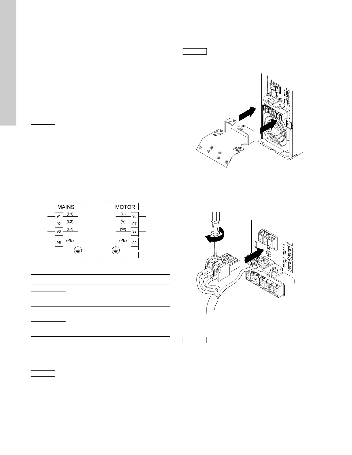
7.2.2 Wiring diagram
The wires in the terminal box must be as short as possible.
Excepted from this is the protective conductor which must be so
long that it is the last one to be disconnected in case the cable is
inadvertently pulled out of the cable entry.
Fig. 6 Wiring diagram, three-phase mains connection
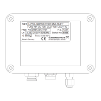
7.2.3 Mains connection, enclosures A2 and A3
For information about enclosures, see table in section
17.1 Enclosure.
1. Fit the mounting plate with two screws.
Fig. 7 Fitting the mounting plate
2. Connect the ground conductor to terminal 95 (PE) and the
mains conductors to terminals 91 (L1), 92 (L2), 93 (L3) of the
mains plug. Put the mains plug into the socket marked
MAINS.
Fig. 8 Connecting the ground conductor and mains
conductors
The maximum output voltage of the CUE is equal
to the input voltage.
Example: If the supply voltage is 208 V, choose a
208 V rated motor.
TM03 8799 2507
Terminal Function
91 (L1)
Three-phase supply92 (L2)
93 (L3)
95/99 (PE) Ground connection
96 (U)
Three-phase motor connection, 0-100 % of
mains voltage
97 (V)
98 (W)
For single-phase connection, use L1 and L2.
Cable sizing:
To determine the conductor gauge size for the
single-phase mains input cable, multiply the
CUE’s max. current output by 2, and choose the
gauge size based on that amperage.
For three-phase input, use the same conductor
gauge size as selected for the motor.
For CUE to motor, use standard published three-
phase wiring charts based on motor size.
Check that the mains voltage and frequency
correspond to the values on the nameplate of the
CUE and the motor.
TM03 9010 2807TM03 9011 2807
For single-phase connection, use L1 and L2.