37
English (US)
14.2 External setpoint
The setpoint can be remote-set by connecting an analog signal
transmitter to the setpoint input (terminal 53).
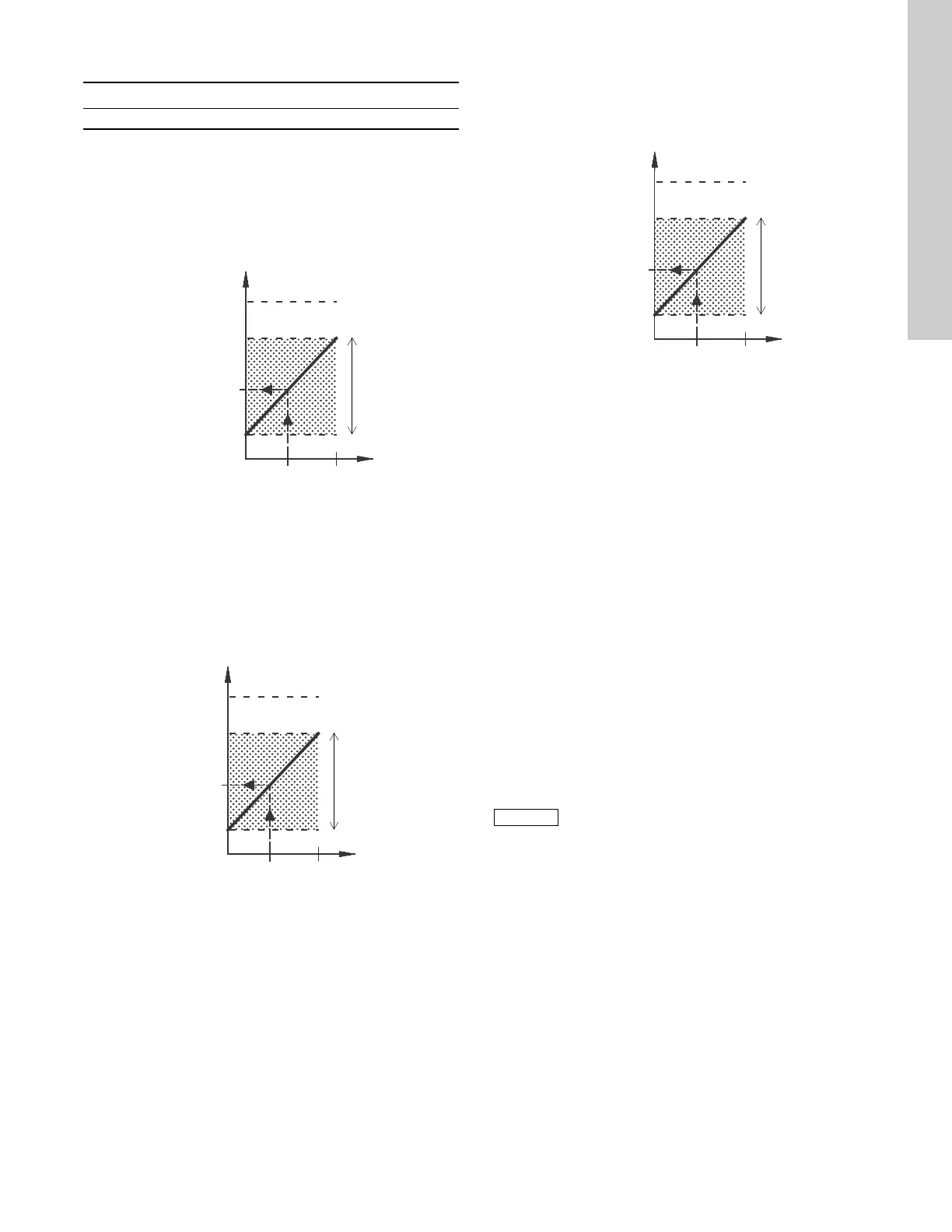
Open loop
In "Open loop" control mode (constant curve), the actual setpoint
can be set externally within the range from the min. curve to the
setpoint set via the CUE menu. See fig. 55.
Fig. 55 Relation between the actual setpoint and the external
setpoint signal in "Open loop" control mode
Closed loop
In all other control modes, except proportional differential
pressure, the actual setpoint can be set externally within the
range from the lower value of the sensor measuring range
(sensor min.) to the setpoint set via the CUE menu. See fig. 56.
Fig. 56 Relation between the actual setpoint and the external
setpoint signal in "Controlled" control mode
Example: At a sensor min. value of 0 psi (0 bar), a setpoint set
via the CUE menu of 43.5 psi (3 bar) and an external setpoint of
80 %, the actual setpoint will be as follows:
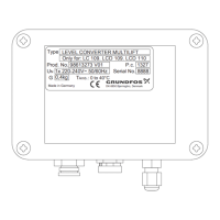
Proportional differential pressure
In "Proportional differential pressure" control mode, the actual
setpoint can be set externally within the range from 25 % of
maximum head to the setpoint set via the CUE menu. See fig. 57.
Fig. 57 Relation between the actual setpoint and the external
setpoint signal in "Proportional differential pressure"
control mode
Example: At a maximum head of 40 ft. (12 meters), a setpoint of
20 ft. (6 meters) set via the CUE menu and an external setpoint of
40 %, the actual setpoint will be as follows:
14.3 GENIbus signal
The CUE supports serial communication via an RS-485 input.
The communication is carried out according to the Grundfos
GENIbus protocol and enables connection to a building
management system or another external control system.
Operating parameters, such as setpoint and operating mode, can
be remote-set via the bus signal. At the same time, the pump can
provide status information about important parameters, such as
actual value of control parameter, input power and fault
indications.
Contact Grundfos for further details.
14.4 Other bus standards
Grundfos offers various bus solutions with communication
according to other standards.
Contact Grundfos for further details.
15. Maintenance and service
15.1 Cleaning the CUE
Keep the cooling fins and fan blades clean to ensure sufficient
cooling of the CUE.
15.2 Service parts and service kits
For further information on service parts and service kits, visit
www.grundfos.com > Grundfos Product Center.
Terminal Type Function
53 AI 1 • External setpoint (0-10 V)
TM03 8856 2607TM03 8856 2607
Actual setpoint = (setpoint set via the CUE menu - sensor min.) x
% external setpoint signal + sensor min.
= (3 - 0) x 80 % + 0
= 34.8 psi (2.4 bar)
Setpoint
Max. curve
Setpoint, CUE menu
Min. curve
Ext. setpoint signal
Actual setpoint
0 10 V
Actual
setpoint
range
Setpoint
Sensor max.
Setpoint, CUE menu
Sensor min.
Ext. setpoint signal
Actual setpoint
0 10 V
Actual
setpoint
range
TM03 8856 2607
Actual setpoint = (setpoint, CUE menu - 25 % of maximum head)
x % external setpoint signal + 25 % of maximum
head
= (6 - 12 x 25 %) x 40 % + 12/4
= 14 ft. (4.2 meters)
If a bus signal is used, the number of settings
available via the CUE will be reduced.
Setpoint
90 % of max. head
Setpoint, CUE menu
25 % of max. head
Ext. setpoint signal
Actual setpoint
010 V
Actual
setpoint
range