English (US)
10
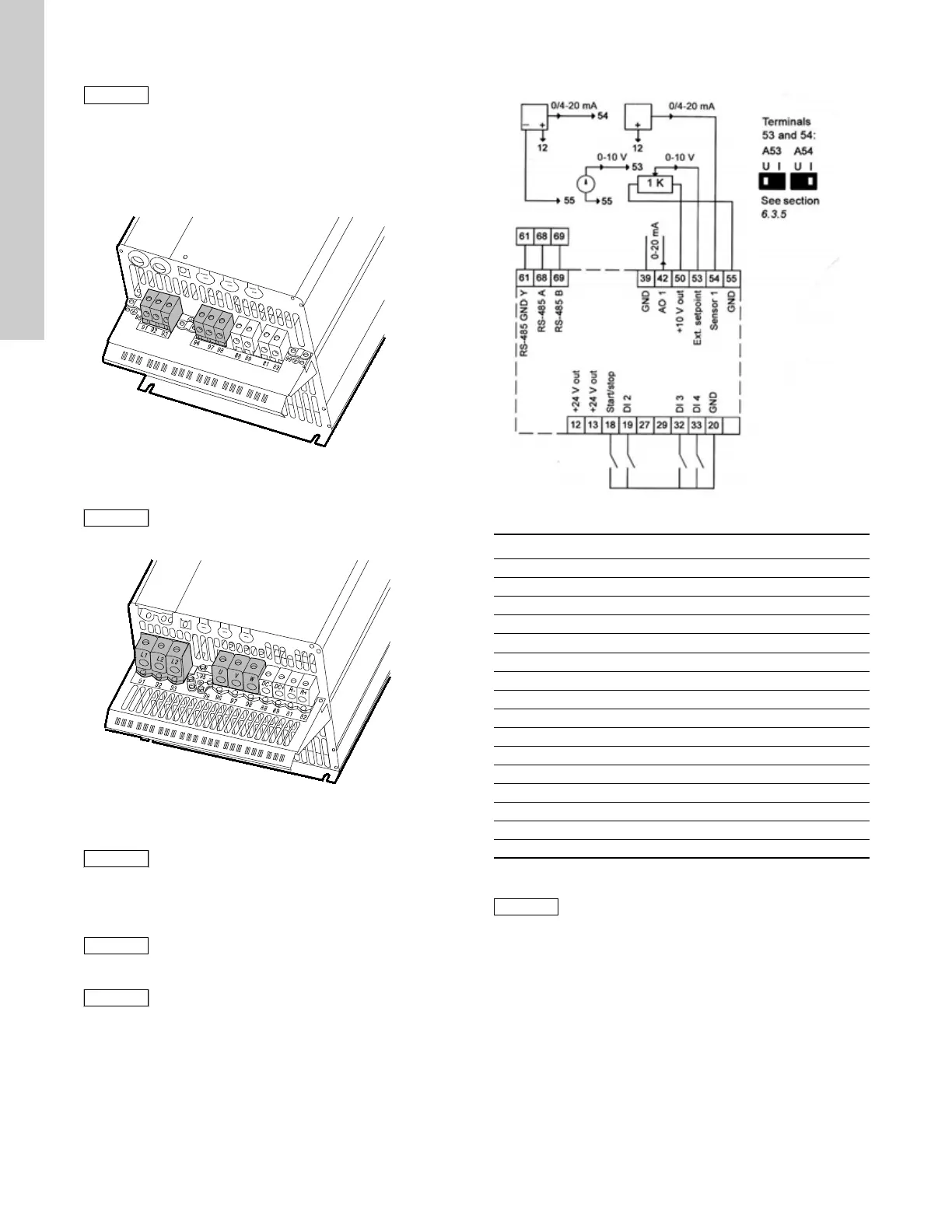
Motor connection
1. Connect the ground conductor to terminal 99 (PE).
See figs 19 and 20.
2. Connect the motor conductors to terminals 96 (U), 97 (V),
98 (W).
3. Fix the screened cable with a cable clamp.
Fig. 19 Mains and motor connection, C3
Fig. 20 Mains and motor connection, C4
7.3 Connecting the signal terminals
Connect the signal cables according to the guidelines for good
practice to ensure EMC-correct installation. See section
7.6 EMC-correct installation.
• Use screened signal cables with a conductor gauge size of
min. 22 AWG (0.5 mm
2
) and max. 16 AWG (1.5 mm
2
).
• Use a 3-conductor screened bus cable in new systems.
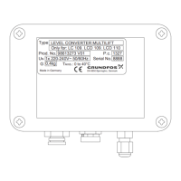
7.3.1 Wiring diagram, signal terminals
Fig. 21 Wiring diagram, signal terminals
Terminals 27, 29 and 37 are not used.
The motor cable must be screened for the CUE to
meet EMC requirements.
TM03 9448 4007
The cable screen must be exposed and in
physical contact with the mounting plate and
clamp.
TM03 9447 4007
The cable screen must be exposed and in
physical contact with the mounting plate and
clamp.
As a precaution, signal cables must be separated
from other groups by reinforced insulation in
their entire lengths.
If no external on/off switch is connected, short-
circuit terminals 18 and 20 using a short wire.
TM06 3250 1214
Terminal Type Function
12 +24 V out Supply to sensor
13 +24 V out Additional supply
18 DI 1 Digital input, start/stop
19 DI 2 Digital input, programmable
20 GND Ground for digital inputs
32 DI 3 Digital input, programmable
33 DI 4 Digital input, programmable
39 GND Ground for analog output
42 AO 1 Analog output, 0-20 mA
50 +10 V out Supply to potentiometer
53 AI 1 External setpoint, 0-10 V / 0/4-20 mA
54 AI 2 Sensor input, sensor 1, 0/4-20 mA
55 GND Ground for analog inputs
61 RS-485 GND Y GENIbus, GND
68 RS-485 A GENIbus, signal A (+)
69 RS-485 B GENIbus, signal B (-)
The RS-485 screen must be connected to ground.