English (US)
14
7.5 Connecting the MCB 114 sensor input module
The MCB 114 is an option offering additional analog inputs for the
CUE.
7.5.1 Configuration of the MCB 114
The MCB 114 is equipped with three analog inputs for these
sensors:
• One additional sensor 0/4-20 mA. See section 11.7.13 Sensor
2 (3.16).
• Two Pt100/Pt1000 temperature sensors for measurement of
motor bearing temperature or an alternative temperature, such
as liquid temperature. See sections 11.7.18 Temperature
sensor 1 (3.21) and 11.7.19 Temperature sensor 2 (3.22).
When the MCB 114 has been installed, the CUE will automatically
detect if the sensor is Pt100 or Pt1000 when it is switched on.
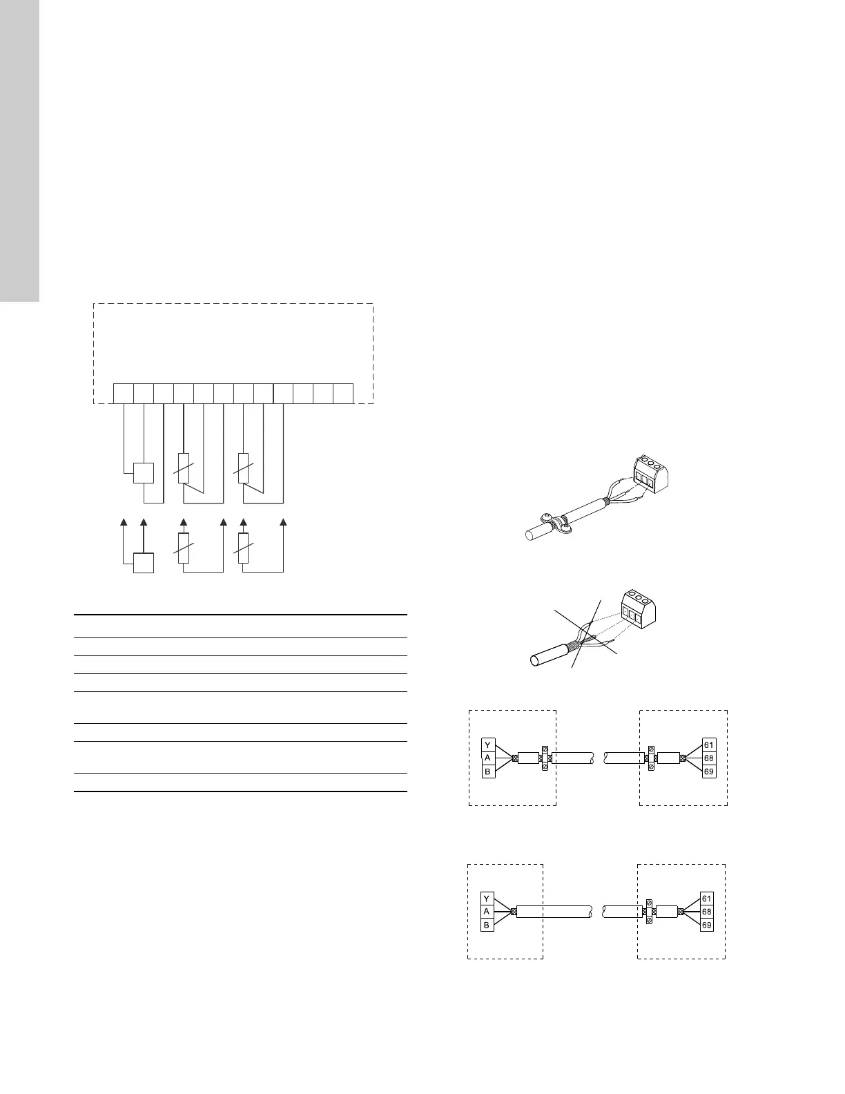
7.5.2 Wiring diagram, MCB 114
Fig. 36 Wiring diagram, MCB 114
Terminals 10, 11 and 12 are not used.
7.6 EMC-correct installation
This section provides guidelines for good practice when installing
the CUE. Follow these guidelines to meet EN 61800-3, first
environment.
• Use only motor and signal cables with a braided metal screen
in applications without output filter.
• There are no special requirements to supply cables, apart
from local requirements.
• Leave the screen as close to the connecting terminals as
possible. See fig. 37.
• Avoid terminating the screen by twisting the ends. See fig. 38.
Use cable clamps or EMC screwed cable entries instead.
• Connect the screen to ground at both ends for both motor and
signal cables. See fig. 39. If the controller has no cable
clamps, connect only the screen to the CUE. See fig. 40.
• Avoid unscreened motor and signal cables in electrical
cabinets with variable frequency drives.
• Make the motor cable as short as possible in applications
without output filter to limit the noise level and minimize
leakage currents.
• Screws for frame connections must always be tightened
whether a cable is connected or not.
• Keep main cables, motor cables and signal cables separated
in the installation, if possible.
Other installation methods may give similar EMC results if the
above guidelines for good practice are followed.
Fig. 37 Example of stripped cable with screen
Fig. 38 Do not twist the screen ends
Fig. 39 Example of connection of a 3-conductor bus cable with
screen connected at both ends
Fig. 40 Example of connection of a 3-conductor bus cable with
screen connected at the CUE (controller with no cable
clamps)
TM04 3273 3908
Terminal Type Function
1 (VDO) +24 V out Supply to sensor
2 (I IN) AI 3 Sensor 2, 0/4-20 mA
3 (GND) GND Ground for analog input
4 (TEMP)
5 (WIRE)
AI 4 Temperature sensor 1, Pt100 / Pt1000
6 (GND) GND Ground for temperature sensor 1
7 (TEMP)
8 (WIRE)
AI 5 Temperature sensor 2, Pt100 / Pt1000
9 (GND) GND Ground for temperature sensor 2
1 98765432
1
2
1
1
1
0
VDO
I IN
GND
TEMP
WIRE
GND
TEMP
WIRE
GND
+
-
+
TM02 1325 0901TM03 8812 2507TM03 8732 2407TM03 8731 2407