15
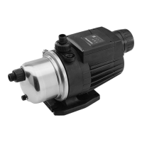
Fig. 6 DMH 257
8.1.1 Combined overpressure and degassing valve
The combined overpressure and degassing valve (M) opens if
there is an excessive pressure build-up in the dosing system and
provokes the constant degassing of the hydraulic medium.
8.1.2 Diaphragm protection system AMS
The diaphragm protection system AMS (9p) has a keypad, which
is connected to the dosing diaphragm. The dosing diaphragm
oscillates freely in the dosing head and cannot be overstretched
due to a fault in the dosing system since the diaphragm protection
valve closes if such a fault occurs.
8.1.3 Double-diaphragm system / diaphragm leakage
detection (optional)
General
The piston diaphragm and high-tech dosing pumps with drift-free
diaphragm leakage detection are equipped with the following:
• dosing head with PTFE double-diaphragm system
• ball non-return valve with built-in contact pressure gauge.
Double-diaphragm system
Dosing pumps with a double-diaphragm system with no
diaphragm leakage detection have no pressure gauge. In this
case the ball non-return valve is fitted with a locking unit. The
valve, however, can be retrofitted with a contact pressure gauge.
Ball non-return valve
In order for the diaphragm leakage detection to work and to
protect the diaphragms, the gap must be fully deaerated. Dosing
heads with a double diaphragm are equipped with a ball non-
return valve (T) to prevent air from flowing back during the filling
and deaeration process (2u).
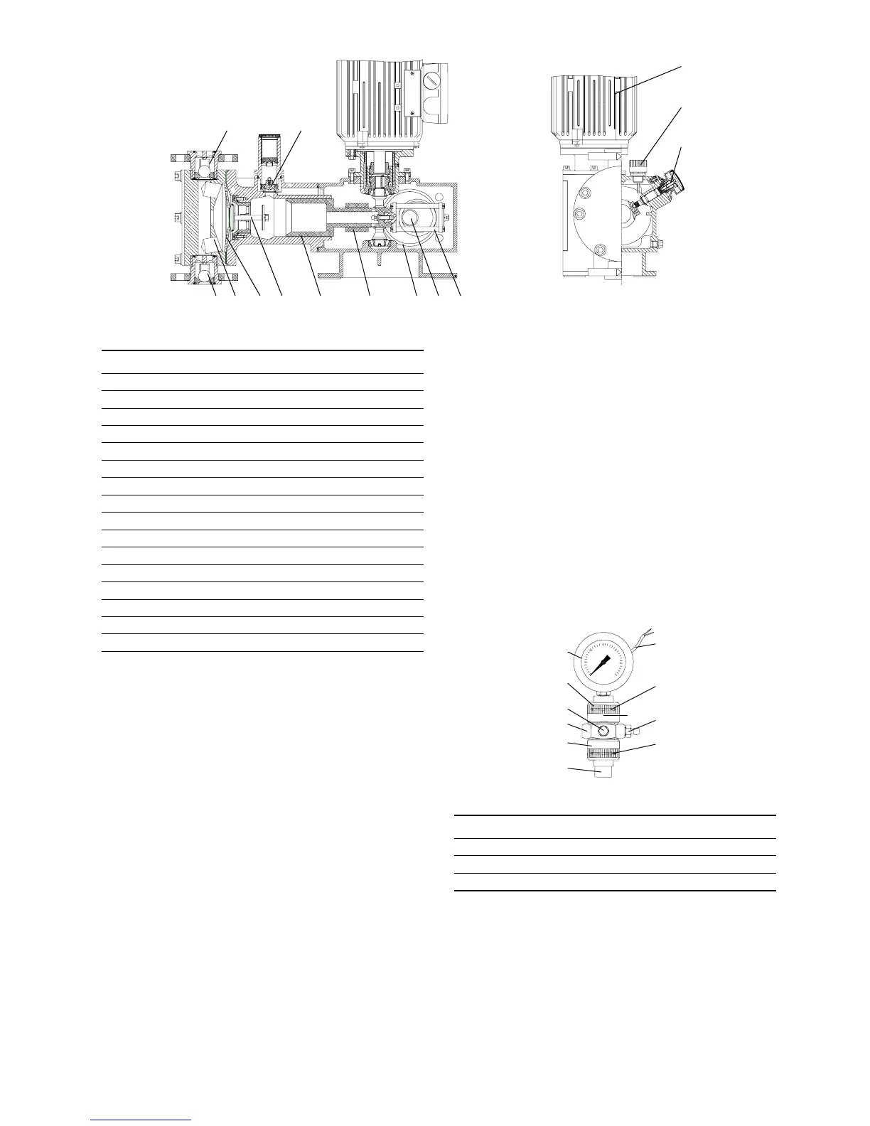
Fig. 7 Contact pressure gauge
2) For dosing heads with a double diaphragm with no contact
pressure gauge (no diaphragm leakage detection), a locking
unit is fitted instead of the contact pressure gauge.
TM03 6452 4506
1p
F
L
M3b
3a 9p 3p2p5p6p2Q 7p
Pos. Components
1p Motor
2p Worm gearing
3p Eccentric
4p Recuperating spring (not with drive size 3)
5p Sliding plug
6p Piston
7p Crank
M Combined overpressure and degassing valve
E Degassing valve
9p Diaphragm protection system (AMS)
Q Dosing diaphragm
2 Dosing head
3a Suction valve
3b Discharge valve
L Stroke-length adjustment knob
F Oil-filling screw with dipstick
TM03 6453 4506
Pos. Components
S Contact pressure gauge
T Ball non-return valve
U Connection piece
T
5u
4u
3u
2)
U
5s
3u
2u
S
6s
 Loading...