27
11.5 Zero point adjustments
11.5.1 Adjusting the zero point for system pressures up to
100 bar
The zero point of the dosing pump is factory-set to a slightly lower
counter-pressure than the rated pressure of the pump. If the
operating counter-pressure deviates considerably from this value,
an adjustment of the zero point will ensure more precise values.
Counter-pressure at the factory-set zero point of the pump
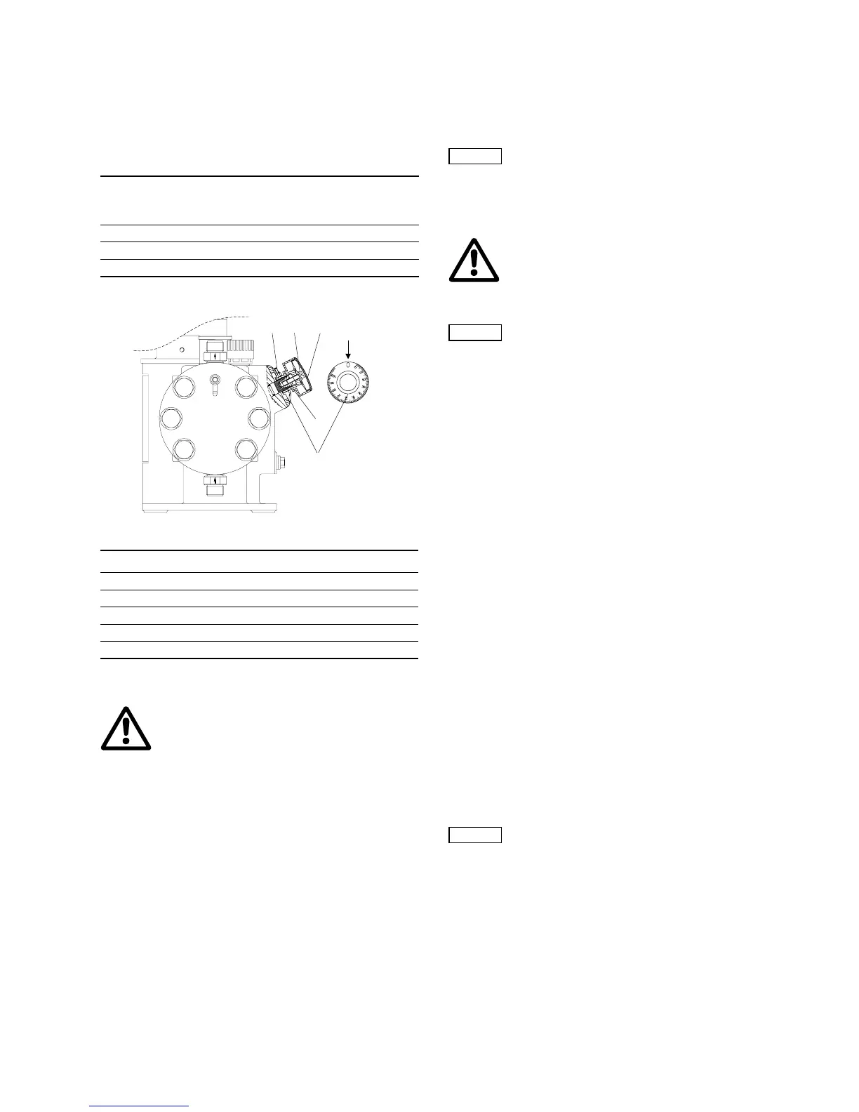
11.5.2 Adjusting the zero point
Fig. 30
Adjusting the zero point
1. Fit a measuring device on the suction side, for instance place
the suction line in a graduated measuring beaker.
2. Set the dosing flow to 15 %.
3. Remove the cover (1l) from the stroke-length adjustment knob
(L).
4. Use a screwdriver to loosen the locking screw (2l) by
approximately 2 turns.
5. Switch on the pump.
6. Slowly turn the stroke-length adjustment knob towards the
zero point until the dosing (the liquid level falls) stops in the
measuring device.
7. Switch off the pump.
8. Set the scale ring (4l) to zero.
– Loosen the screw (3l) in the scale ring (4l) slightly using an
hexagon key, M3.
– Turn the scale ring (4l) until both "0" are the same on the
scale and scale ring.
– Tighten the screw (3l).
9. Depending on the application, tighten the locking screw (2l) so
that the stroke-length adjustment knob can still be turned/
cannot be turned any more.
10.Replace the cover (1l).
11.6 Operating the pump
11.7 Shutdown
11.7.1 Switching off / uninstalling
1. Switch off the pump and disconnect it from the power supply.
2. Depressurise the system.
3. Take suitable steps to ensure that the returning dosing
medium is safely collected.
4. Carefully remove all lines.
5. Uninstall the pump.
11.7.2 Cleaning
1. Rinse all parts that have come into contact with the medium
very carefully:
– lines
– valves
– dosing head
– diaphragm.
2. Remove any trace of chemicals from the pump housing.
11.7.3 Storage
Storage of the pump:
1. After cleaning (see section
11.7.2 Cleaning), carefully dry all
parts and reinstall the dosing head and valves, or
2. change the valves and diaphragm.
See section
13. Maintenance.
11.7.4 Disposal
Disposal of the pump:
• After cleaning (see section
11.7.2 Cleaning), dispose of the
pump in accordance with the relevant regulations.
12. Operation
12.1 Switching on/off
• To start the pump, switch on the power supply.
• To stop the pump, switch off the power supply.
Rated pressure of the pump
[bar]
Counter-pressure at the
factory-set zero point
[bar]
10 3
16 3
25 10
TM03 6466 4506
Pos. Components
L Stroke-length adjustment knob
1l Cover
2l Locking screw
3l Screw
4l Scale ring
Warning
When dosing dangerous media, observe the
corresponding safety precautions!
Wear protective clothing (gloves and goggles)
when working on the dosing head, connections
or lines!
Always adjust the value with the discharge line
connected and with operating counter-pressure.
3l 2l 1l
4l
3l
L
Note
When operating the pump, see sections
12. Operation and 13. Maintenance and,
if necessary, section 14. Fault finding chart.
Warning
Wear protective clothing (gloves and goggles)
when working on the dosing head, connections
or lines!
Do not allow any chemicals to leak from the
pump. Collect and dispose of all chemicals
correctly!
Note
If possible, rinse the dosing head before shutting
down the pump, e.g. by supplying it with water.
Caution
Before switching on the pump, check that it is
installed correctly. See sections 9. Installation
and 11. Start-up / shutdown.
 Loading...


