22
Fig. 15 Installation with discharge-side pulsation damper
• For degassing and viscous media: flooded suction.
• Install a filter in the suction line to prevent the valves from
becoming choked.
• To protect the dosing pump and the discharge line against
excessive pressure build-up, install a relief valve (6i) in the
discharge line.
Fig. 16 Installation with relief valve
With open outflow of the dosing medium or a counter-
pressure below 2 bar
• Install a pressure-loading valve (7i) immediately before the
outlet or the injection unit.
A positive pressure difference of at least 2 bar must be ensured
between the counter-pressure at the injection point and the
pressure of the dosing medium at the pump suction valve.
• If this cannot be ensured, install a pressure-loading valve (7i)
in the discharge line.
Fig. 17 Installation with pressure-loading valve
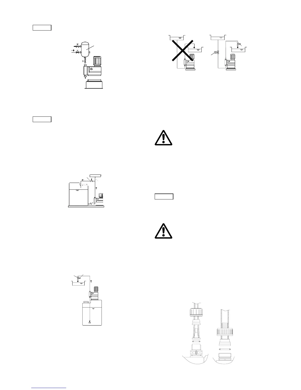
• To avoid the siphon effect, install a pressure-loading valve (7i)
in the discharge line and, if necessary, a solenoid valve (14i) in
the suction line.
Fig. 18 Installation to avoid the siphon effect
9.7 Tube / pipe lines
9.7.1 General
9.8 Connecting the suction and discharge lines
• Connect the suction line to the suction valve.
– Install the suction line in the tank so that the foot valve
remains 5 to 10 mm above the bottom of the tank or the
possible level of sedimentation.
• Connect the discharge line to the discharge valve.
Connection of hose lines
• Push the hose firmly on the connection nipple and, depending
on the connection, secure using a connection counterpart or
hose clip.
• Fit the gasket.
• Screw the hose on the valve using the union nut.
Fig. 19 Connection of hose lines
Note
To protect the system, use pulsation dampers (8i)
for rigid piping longer than 2 metres and tubing
longer than 3 metres, depending on pump type
and size.
TM03 6301 4506
Caution
Risk of damage to the system!
It is always recommended to use pulsation
dampers for large high-speed pumps!
Since the pulsation is influenced by many
factors, a system-specific calculation is
essential. Request a calculation from our
calculation program.
TM03 6302 4506TM03 6303 4506
8i
6i
10i
p
7i
p
≥
2 bar
p ≥ 1 bar
TM03 6304 4506
Warning
To protect the dosing system against excessive
pressure build-up, install a relief valve in the
discharge line.
Only use the prescribed line types!
All lines must be free from strain!
Avoid loops and buckles in the tubes!
Keep the suction line as short as possible to
avoid cavitation!
If necessary, use swept bends instead of elbows.
Observe the chemical manufacturer's safety
instructions when handling chemicals!
Make sure that the pump is suitable for the actual
dosing medium!
The flow must run in the opposite direction to
gravity!
Caution
The resistance of the parts that come into contact
with the media depends on the media, media
temperature and operating pressure. Ensure that
parts in contact with the media are chemically
resistant to the dosing medium under operating
conditions!
Warning
All lines must be free from strain!
Only use the prescribed line types!
TM03 6456 4506
14i
p
1
p
2
p
2
- p
1
1 bar
>
_
p
2
-p
1
≥ 1 bar
 Loading...


