25
11.1.3 Filling the dosing head for the initial start-up for
systems without flooded suction
As assisting suction for systems without flooded suction, you can
fill the dosing head with dosing medium before the initial start-up:
1. Unscrew the discharge valve (3b).
2. Add the dosing medium to the dosing head (2).
3. Screw the discharge valve (3b) back in.
11.2 Start-up / subsequent start-up of DMH 251, 252
and 253
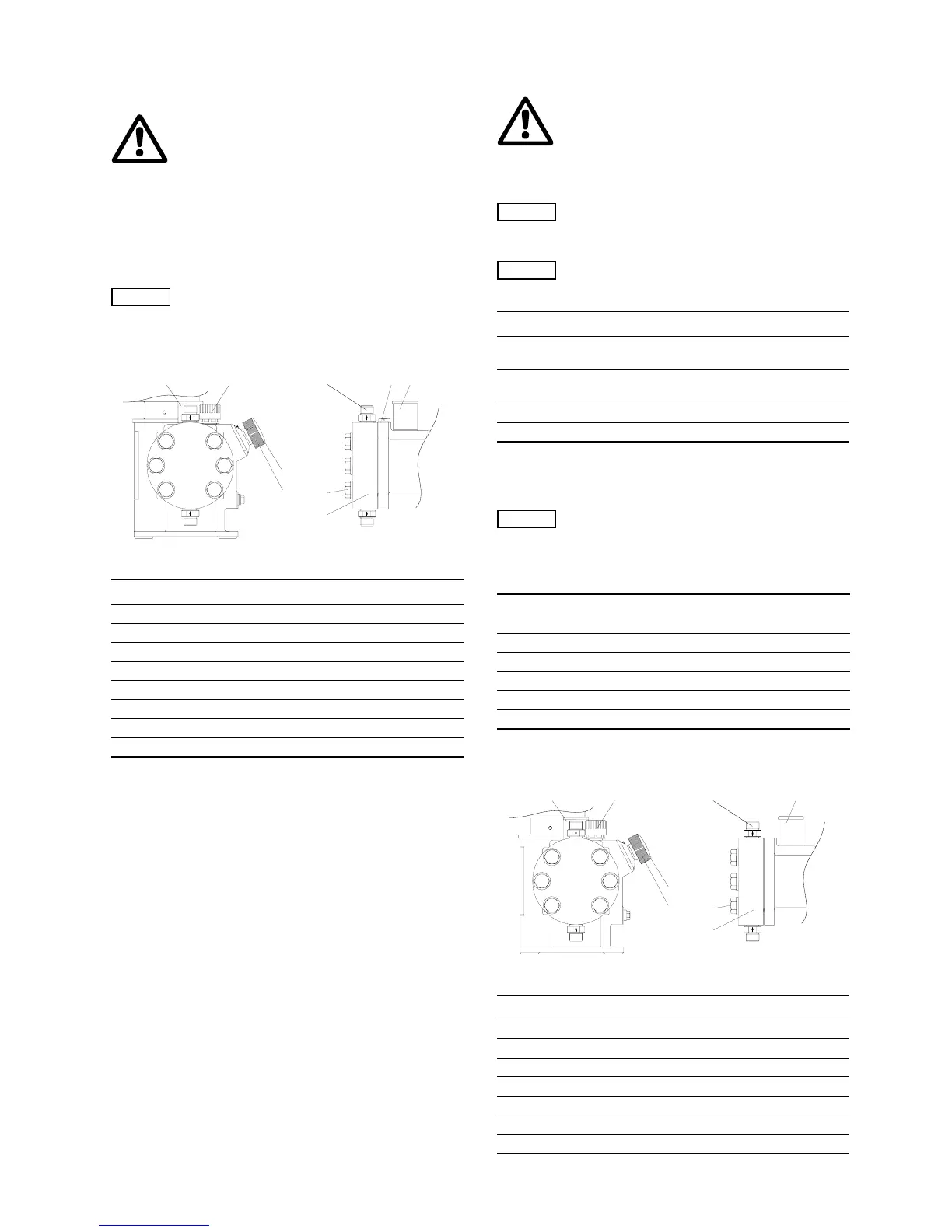
Fig. 26 Start-up of DMH 251, 252 and 253
1. Connect the electrical power supply.
2. Depending on the installation, start the pump, where possible,
without counter-pressure.
See installation example for easy deaeration of the dosing head
in section
9. Installation.
3. Set the stroke-length adjustment knob (L) to 0 %.
4. Let the pump run for approx. 5 minutes.
5. Check the oil level.
– Set the stroke-length adjustment knob (L) to 40 %.
– Let the pump run for approx. 10 minutes with a stroke-length
setting of 40 %.
– Switch off the pump, check the oil level and add oil,
if necessary.
– Refit the oil-filling screw (F).
6. Deaerate the piston flange.
– Set the stroke-length adjustment knob (L) to 15 %.
– Loosen the degassing valve (E) by one turn to the left.
– Let the pump run for approx. 5 minutes.
– Re-tighten the degassing valve (E).
The pump is now ready for operation.
After start-up
Torques
11.3 Start-up / subsequent start-up of DMH 254, 255
and 257
Fig. 27 Start-up of DMH 254, 255 and 257
Warning
When dosing dangerous media, observe the
corresponding safety precautions!
Wear protective clothing (gloves and goggles)
when working on the dosing head, connections
or lines!
Note
Observe the flow direction of the discharge valve
(indicated by an arrow on the valve)!
TM03 6462 4506
Pos. Components
1q Dosing head screws
2 Dosing head
3b Discharge valve
E Degassing valve
F Oil-filling screw with dipstick
L Stroke-length adjustment knob
1l Cover for stroke-length adjustment knob
M Pressure relief valve
L
F
1l
2
M M
1q
E
3b
Warning
Risk of injury caused by squirting oil!
Oil may squirt from the oil deaeration when the
pump is running. Do not completely unscrew the
oil deaeration screw.
Wear protective clothing (gloves and goggles)
when working on the dosing head, connections
or lines!
Note
Rod length of oil dipstick: 27 mm.
Immersion depth to marking: approx. 5 mm.
Note
Check the oil level at least every two weeks and
add oil, if necessary.
Only use original Grundfos Alldos gear oil!
For product number, see service instructions.
Pump type Version Description
DMH 251 Single/double
1.3 l white oil
(Paraffin 55 DAB7)
DMH 252, 10 bar Single/double
1.3 l white oil
(Paraffin 55 DAB7)
DMH 252, 16 bar Single/double 1.3 l DHG 68
DMH 253 Single/double 1.3 l DHG 68
Caution
After initial start-up and after each time the
diaphragm is changed, tighten the dosing head
screws.
After approximately 6-10 operating hours or
two days, cross-tighten the dosing head screws
using a torque wrench.
Pump type
Torque
[Nm]
DMH 251, 10 bar 8-10
DMH 251, 16 bar 10-12
DMH 251, 25 bar 13-15
DMH 252 8-10
DMH 253 10-12
TM03 6463 4506
Pos. Components
1q Dosing head screws
2 Dosing head
3b Discharge valve
F Oil-filling screw with dipstick
L Stroke-length adjustment knob
1l Cover for stroke-length adjustment knob
M Pressure relief valve
L
F
1l
2
M M
1q
3b
 Loading...


