21
9.5 Optimum installation
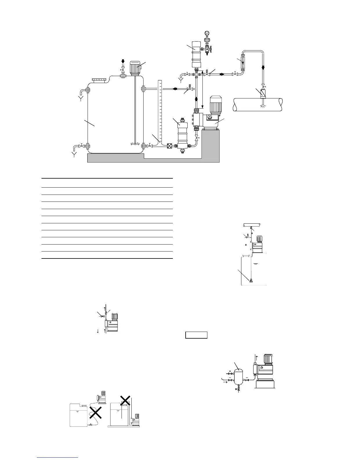
Fig. 10 Example of optimum installation
9.6 Installation tips
• For easy deaeration of the dosing head, install a ball valve
(11i) with bypass line (back to the dosing tank) immediately
after the discharge valve.
• In the case of long discharge lines, install a non-return valve
(12i) in the discharge line.
Fig. 11 Installation with ball valve and non-return valve
• When installing the suction line, observe the following:
– Keep the suction line as short as possible. Prevent it from
becoming tangled.
– If necessary, use swept bends instead of elbows.
– Always route the suction line up towards the suction valve.
– Avoid loops which may cause air bubbles.
Fig. 12 Installation of suction line
• For non-degassing media with a viscosity similar to water, the
pump can be mounted on the tank (observe the maximum
suction lift).
• Flooded suction preferred.
• For media with a tendency to sedimentation, install the suction
line with filter (13i) so that the suction valve remains a few
millimetres above the possible level of sedimentation.
Fig. 13 Tank installation
• Note for suction-side installation: Depending on the dosing
flow and the line length, it may be necessary to install a
properly sized pulsation damper (4i) immediately before the
pump suction valve.
Fig. 14 Installation with suction-side pulsation damper
• Note for discharge-side installation: Depending on the dosing
flow and the line length, it may be necessary to install a
properly sized pulsation damper (4i) on the discharge side.
TM03 6296 4506
1i
2i
3i
4i
5i
6i
7i
9i
10i
8i
max. 1m
Max. 1 m
Pos. Components
1i Dosing tank
2i Electric agitator
3i Extraction device
4i Suction pulsation damper
5i Dosing pump
6i Relief valve
7i Pressure-loading valve
8i Pulsation damper
9i Measuring glass
10i Injection unit
TM03 6297 4506TM03 6298 4506
11i
12i
TM03 6299 4506
Note
Observe section 9.4 Approximate values when
using pulsation dampers and, if necessary,
request a system-specific calculation from our
calculation program.
TM03 6300 4506
p
10i
6i
13i
4i
 Loading...


