16
Counters
The pump can display "non-resettable" counters for:
• "Quantity"
Accumulated dosed quantity in liters or US gallons.
• "Strokes"
Accumulated number of dosing strokes.
• "Hours"
Accumulated number of operating hours (power on).
• "Power ON"
Accumulated number of times the mains supply has
been switched on.
Languages
The display text can be displayed in one of the following
languages chosen in the set-up menu:
• English
•German
•French
•Italian
• Spanish
• Portuguese
•Dutch
• Swedish
• Finnish
•Danish
• Czech
•Slovak
• Polish
• Russian.
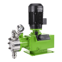
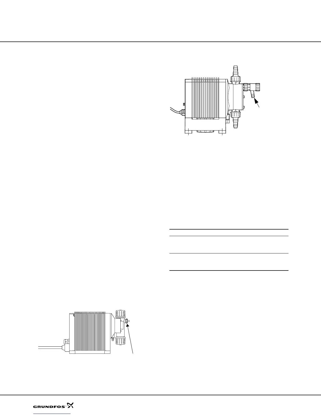
Integrated venting
The DME and DMS dosing pumps are provided with an
integrated vent valve. The valve makes it very easy to
prime the pump during start-up:
The vent valve must be connected to the tank by means
of 1/4" tubing.
For the larger pumps, the vent valve must be connected
to the tank by means of 5/8" ID tubing.
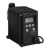
Switch-mode power supply
Applies to DME
The DME pump is incorporates a switch-mode power
supply. This makes the pump independent of variations
in supply voltage and frequency. Operating range: 1 x
100-240 V, 50-60 Hz.
Level control
Applies to DME-A and DMS-A
The pump can be connected to a level control unit for
monitoring of the chemical level in the tank.
The pump can react to two level signals. The following
table shows the pump reactions to the sensor signals:
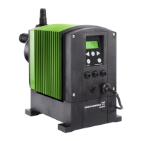
Bus communication
Applies to DME
The pump is available with an optional built-in module
for bus communication with GENIbus (variant AG, DME
2 to 48 only) or PROFIBUS (variant AP) systems.
These modules enable remote monitoring and setting
via the fieldbus system. All DME features are available
via bus communication. The PROFIBUS GDS-file can
be downloaded from www.grundfos.com/dosing.
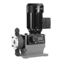
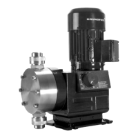
Diaphragm leakage sensor (DME 60 to 940)
The pump can be fitted with a leak sensor that connects
to the drain hole of the pump head. In the event of
diaphragm leakage, the sensor will activate the pump's
alarm relay.
TM01 8420 5099
Vent valve
TM02 7066 2503
Level sensors Pump reaction
Upper sensor activated
• Red indicator light is on.
• Pump running.
• Alarm relay activated.
Lower sensor activated
• Red indicator light is on.
• Pump stopped.
• Alarm relay activated.
Applies to control variant AR
Vent valve
DME 60 to 940
Functions
DME and DMS
Dm123.book Page 16 Tuesday, February 8, 2005 8:24 AM
 Loading...