6
Functions
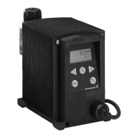
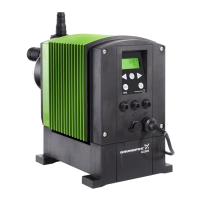
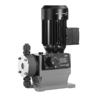
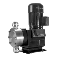
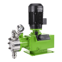
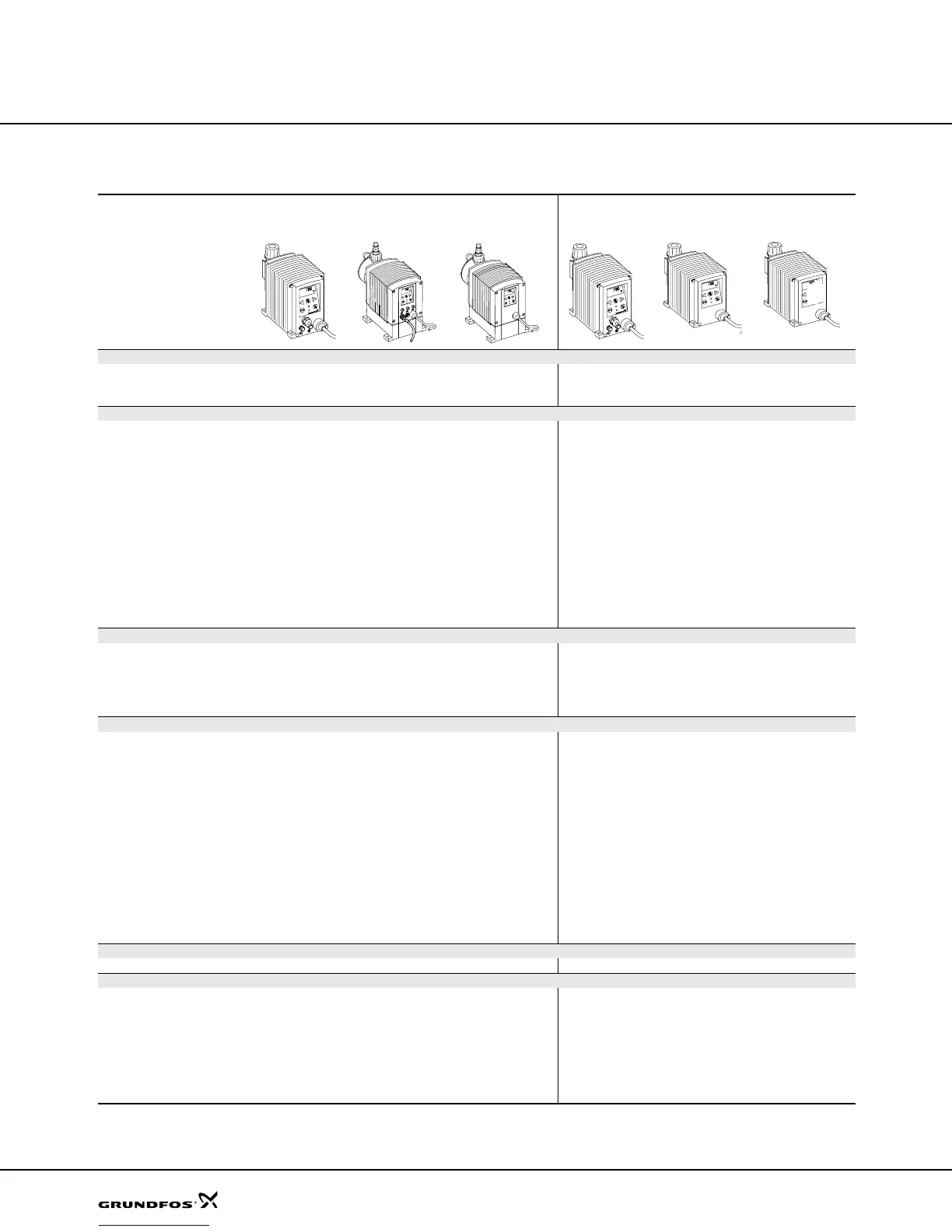
DME and DMS
Overview of functions
DME DMS
2 to 48 60 to 940 AR 60 to 940 B variant A variant B variant D
TM01 8941 0900
TM02 8337 4903
TM02 8338 4903
TM01 8941 0900
TM01 8943 0900
TM02 8973 1304
Capacity control, see page 8
Internal stroke frequency
control
zzzzz
Internal stroke speed control zzz
Control panel, see page 10
Capacity setting in liters,
milliliters or US gallons
zzzzz
Display with background light
and soft-touch buttons
zzzzz
Easy set-up menu with
language options
zzzzz
On/off button zzzzz
Maximum capacity button
(priming)
zzzzz
Green indicator light for
operating indication
zzzzz
Red indicator light for
fault indication
zzzzz
Control panel lock zzzzz
Side-fitted as an option zzzz
Operating modes, see page 13
Manual control zzzzz
Pulse control zz z
Analog 0/4-20 mA control zz z
Timer-based batch control zz
Pulse-based batch control zz
Functions, see page 17
Dosing monitoring zz z
Dual-level control zz z
Calibration of pump to actual
installation
zzzzz
Anti-cavitation
(reduced suction speed)
zzz
Capacity limitation zzz
Counters for strokes, operating
hours and power on/off
zzzzz
Fieldbus communication
(variants AP and AG)
zz
Overload protection zz
Error message in display zz
Leakage sensor z
Dosing signal output z
Power supply, page 16
Switch-mode power supply zzz
Inputs/outputs, see page 19
Input for pulse control zz z
Input for analog 0/4-20 mA
control
zz z
Input for dual-level control zz z
Input for external start/stop zz z
Alarm relay output (variant AR) zz z
Dosing output z
Input for external on/off switch zz z
Dm123.book Page 6 Tuesday, February 8, 2005 8:24 AM
 Loading...