English (GB)
7
4. Product description
The controller is placed in a control cabinet with fixing holes at
the back and in the bottom for mounting. The cabinet can either
be mounted on a pump set or a wall.
The control cabinet, which is powered by the mains, supplies the
electric motor with power.
4.1 Controls and indicating instruments
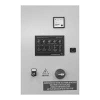
All controls and indicating instruments are placed in the cabinet
door. See fig. 1.
Fig. 1 Cabinet door
The control elements and indicator lights have the following
functions:
Ammeter (pos. 1)
The ammeter indicates the current consumption of the electric
motor.
Control panel (pos. 2)
The control panel contains the buttons required for control and
various indicator lights. See section 8. Control panel.
Selector switch (pos. 3)
The selector switch is used to select the operating mode
(manual or automatic). The selector switch must be locked to
prevent unauthorised activation. When the main switch is set to
"I", the power supply to the electric motor is provided via the
selector switch.
Main switch (pos. 4)
The main switch is used to switch on the voltage supply to the
control cabinet.
4.2 Main components in control cabinet
The main components in the control cabinet are shown in fig. 2.
Fig. 2 Main components in control cabinet
Inputs and outputs
The inputs and outputs are listed in section 7. Technical data.
TM05 0741 1511
Pos. Designation
1 Ammeter
2 Control panel
3 Lockable selector switch (Test - 0 - Auto)
4 Main switch
TM05 0742 1511
Pos. Designation
F1 Main fuse
FA2 Fuse for 24 V control circuit
FA3 Fuse for 230 V control circuit
FV Fuse for transformer
K1L Mains contactor
K1D Delta contactor
K1Y Star contactor
KA1 Relay for monitoring of control voltage
KT0 Time relay (optional)
KT1 Time relay
KSFL Phase-monitoring relay
KSFM Phase-monitoring relay for motor terminals
PE Protective conductor bar
Q1 Main switch
TA Current transformer for measuring the motor current
TR Transformer (400/24 V) for control voltage
TR1 Transformer (400/230 V) for control voltage

 Loading...