English (GB)
9
6.2 Type key
The example shows a controller for electrically driven pumps in
accordance with EN 12845 with a motor output of 15 kW.
7. Technical data
Inputs
The controller has four digital inputs. See table below. The table
also states terminal designations and the status when activated.
The digital inputs are not short-circuit proof.
Outputs
The controller has five digital outputs which are potential-free
changeover contacts. The signals from the digital outputs can be
passed on to a building management system.
Electrical data of signal relay outputs
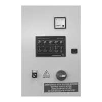
8. Control panel
The control panel is divided into three areas:
• operating buttons
• status indicator lights
• fault indicator lights.
Fig. 4 Control panel
8.1 Button functions
Example QST EN / 1 x 15 kW
Type range
Controller for electrically driven pumps
Controller approval
EN: in accordance with EN 12845
Number of connectable electric motors
Performance of connectable electric motor(s)
Control cabinet: Sheet steel, grey.
Enclosure class: IP54.
Dimensions w x h x d: 400 x 600 x 250 mm.
Weight: Up to approx. 80 kg.
Supply voltage: 3 x 400 V, 50 Hz, PE.
Max. current consumption: See wiring diagram.
Back-up fuse: Max. 20 A.
Connecting terminals: L1, N = 2.5 - 6 mm
2
.
EMC noise emission: According to EN 61000-6-3.
EMC noise immunity: According to EN 61000-6-2.
Overvoltage category: III.
Rated short-circuit current: 6 kV.
Degree of contamination: 2.
Ambient temperature: 5 to +40 °C.
Production country: Italy.
Designation Digital input Terminal
Upon
activation
DI1 Pressure switch 1 6 + 7 Open
DI2 Pressure switch 2 8 + 9 Open
DI3
Priming tank level switch
(for starting the pump)
10 + 11 Closed
DI4
Additional pressure
switch for "Pump
running" indication
(pressure in the
discharge line)
12 + 13 Closed
Designation Digital output Terminal
Upon
activation
AR1
Alarm, voltage supply to
controller
31 + 32 Open
AR2
Automatic pump
requirement
33 + 34 Closed
AR3 Pump running 35 + 36 Closed
AR4
Alarm, voltage supply to
motor
37 + 38 Closed
AR5 Failure to start 39 + 40 Closed
Voltage class: Category 1.
Insulation voltage: 115 V (in relation to earth).
Insulation test voltage: 1.5 kVAC.
Max. supply voltage: 115 VAC.
Max. load: 2 A, 250 V.
Min. load: 100 mA, 12 VDC.
Max. load power: 230 VA/24 W.
TM05 0744 1511
Button Description
Manual stop of pump (only possible when the
selector switch is set to "Test").
Manual start of pump (only possible when the
selector switch is set to "Test").
Test of pressure switch 1
Test of pressure switch 2
Indicator light test

 Loading...