English (GB)
27
8.4 Communication, control and monitoring
MAGNA1 enables external control and monitoring via the
Start/Stop input, see section 8.4.1 Digital input (Start/Stop), and
the fault relay output, see section 8.4.2 Fault relay output, on
both single and twin-head pumps. In addition, the wireless
communication feature in twin-head pumps lets you use the pump
without an external controller, see section 8.4.3 Twin-head pump
function.
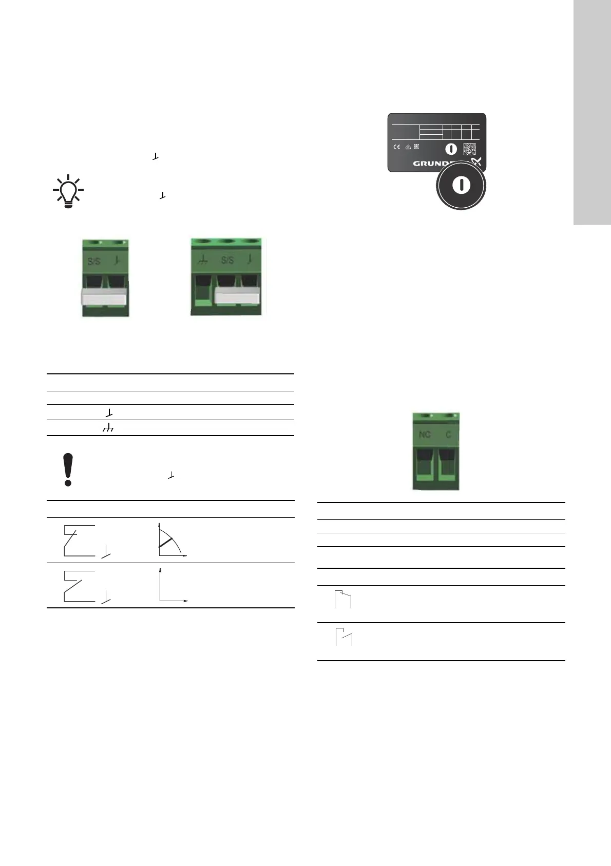
8.4.1 Digital input (Start/Stop)
To use the digital input, connect the control wires to terminals
Start/Stop (S/S) and frame ( ).
Fig. 36 Digital input in the control box
A: Plug-connected versions
B: Terminal-connected versions
For instructions on how to connect to the Start/Stop input, see
section 3.5.5 Connecting the digital input.
Digital input on twin-head pumps
The Start/Stop input operates on system level, meaning that if the
master pump head receives a stop signal, the system stops.
As a main rule the digital input is only effective on the master,
which is why it is important to know which pump is assigned as
the master, see fig. 37.
Fig. 37 Identifying the master pump head on the nameplate
For redundancy purposes, the digital input can be used
concurrent on the slave pump head. However, as long as the
master is powered up, the input on the slave will be ignored. In
the event of power loss on the master, the digital input of the
slave will take over. When the master pump head is back on, the
master takes over and controls the slave.
8.4.2 Fault relay output
It is possible to use the relay output as part of a control strategy
or for monitoring. For example, if the pump experiences a fault,
the fault relay sends a signal to the controller, which will
subsequently trigger further events depending on your chosen
strategy. In order to use the fault relay output, follow the
instructions in fig. 38.
The relay can be used for outputs up to 250 V and 2 A.
Factory settings of the relay:
The functions of the fault relay are as shown in the table:
Fig. 38 Fault relay output table
For instructions on how to connect to the fault relay output, see
section 3.5.6 Connecting the fault relay output.
Fault relay output in twin-head pumps
The fault relay output on each pump head operates
independently, meaning that if a fault occurs in one of the pumps
its respective relay is triggered.
If no external on and off switch is connected,
maintain the jumper between terminals Start/Stop
(S/S) and frame ( ).This connection is the factory
setting.
A
B
TM06 9107 4617 - TM06 9080 3617
Contact symbol Function
S/S Start/Stop
Frame connection
Cable shield
Plug-connected versions, pos. A, fig. 36:
When using a shielded cable, connect the shield in
the frame terminal ( ) together with the frame
connection cord.
Start/Stop
Normal duty
Stop
TM06 8063 0817TM06 9107 4617
Contact symbol Function
NC Normally closed
C Common
Fault relay Alarm signal
Not activated:
• The power supply has been switched off.
• The pump has not registered a fault.
Activated:
• The pump has registered a fault or there is a
wirebreak.
XXXXXXXXXXXXXXXXXXXXXXXX
P/N: XXXXXXXX
S/N: XXXXXXXX
PC: XXXX
Model: X
IP XXX TF XXX
Grundfos Holding A/S, DK - 8850 Bjerringbro, Denmark
((,;;;3DUW;
Made in Germany
0LQ
0D[
;;;
;;
XXXX
XXXX;;;
I
1
[A] P
1 [W] MPa

 Loading...