English (GB)
23
8. Setting the product
8.1 Operating panel
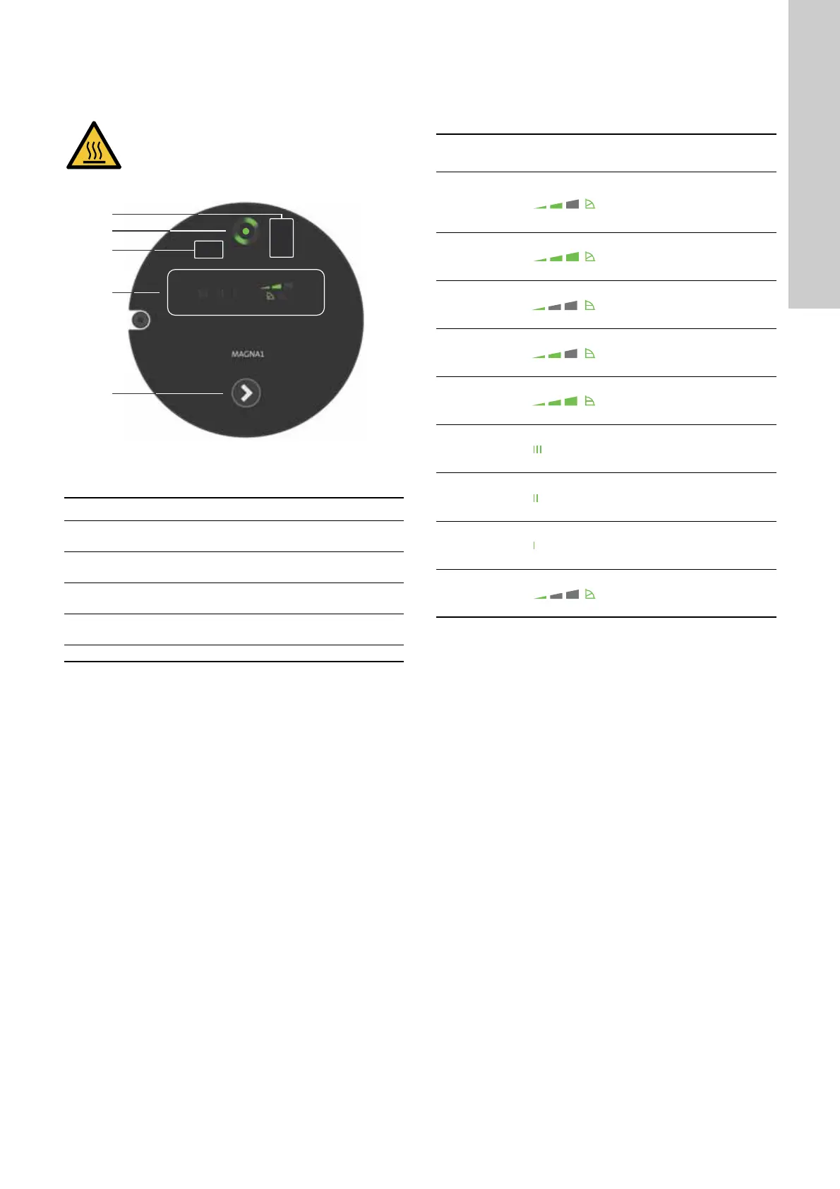
Fig. 30 Operating panel
The operating panel on the pump comprises the following:
8.2 Setting the control function
The pump has nine control functions, see section 7. Control
functions. Select the control function by pressing the push-button
on the operating panel, see fig. 30, pos. 5. The control function is
indicated by eight different light fields in the display.
CAUTION
Hot surface
Minor or moderate personal injury
- To avoid burns only touch the operating panel.
TM06 9078 3617
Pos. Description
1
Infrared receiver for Grundfos GO.
Plug-connected versions.
2
Grundfos Eye.
See section 9.1 Grundfos Eye operating status.
3
Infrared receiver for Grundfos GO.
Terminal-connected versions.
4
LEDs indicate the control function.
See section 8.2 Setting the control function.
5 Push-button for selection of a control function.
Button
presses
Active light fields Description
0
Intermediate
proportional-pressure
curve, referred to as
PP2, factory setting
1
Highest
proportional-pressure
curve, referred to as PP3
2
Lowest
constant-pressure curve,
referred to as CP1
3
Intermediate
constant-pressure curve,
referred to as CP2
4
Highest
constant-pressure curve,
referred to as CP3
5
Constant curve III
6
Constant curve II
7
Constant curve I
8
Lowest
proportional-pressure
curve, referred to as PP1

 Loading...