English (GB)
12
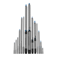
3. Lift the pump part by means of pipe clamps fitted to the
extension pipe. See fig. 21.
Fig. 21 Lifting the pump into position
4. Place the pump part on top of the motor.
5. Fit and tighten the nuts. See table below.
The bolts and nuts securing the straps to the pump must be
cross-tightened to the following torques:
When fitting the motor to the pump part, cross-tighten the nuts to
the following torques:
7.2 Removing and fitting the cable guard
If the cable guard is screwed on to the pump, it should be
removed and fitted by means of screws.
7.3 Connecting the submersible drop cable
7.3.1 Grundfos motors
Before connecting the submersible drop cable to the motor, make
sure that the cable socket is clean and dry.
To facilitate the connection of the cable, lubricate the rubber parts
of the cable plug with non-conducting silicone paste.
Tighten the screws holding the cable to these torques [Nm]:
MS 402: 2.0
MS 4000: 3.0
MS 6000: 4.5
MMS 6: 20
MMS 8000: 18
MMS 10000: 18
MMS 12000: 15
7.4 Riser pipe
If a tool, e.g. a chain pipe wrench, is used when the riser pipe is
fitted to the pump, the pump must only be gripped by the pump
discharge chamber.
The threaded joints on the riser pipe must all be well cut and fit
together to ensure that they do not work loose when subjected to
torque reaction caused by the starting and stopping of the pump.
The thread on the first section of the riser pipe which is to be
screwed into the pump should not be longer than the threads in
the pump.
If noise may be transmitted to the building through the pipework,
we recommend that you use plastic pipes.
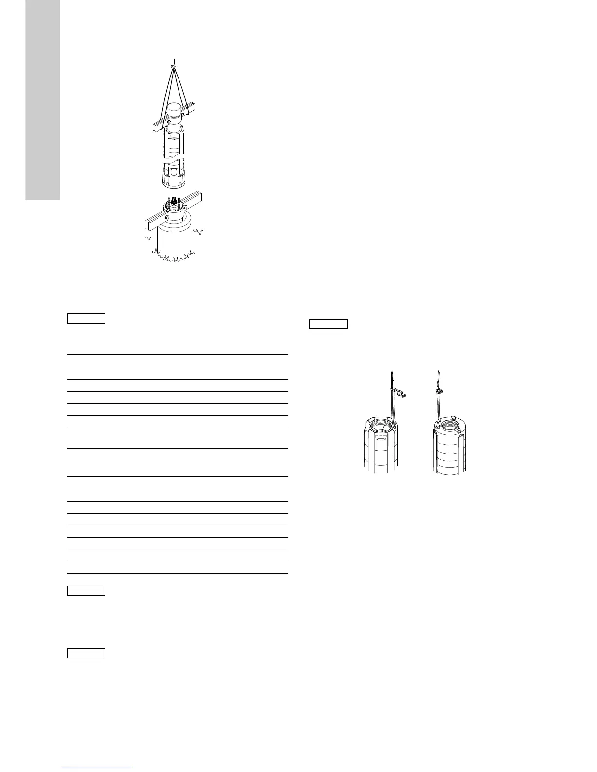
When plastic pipes are used, secure the pump by an unloaded
straining wire to be fastened to the discharge chamber of the
pump. See fig. 22.
Fig. 22 Fixing the straining wire
When connecting plastic pipes, use a compression coupling
between the pump and the first pipe section.
Where flanged pipes are used, the flanges should be slotted to
take the submersible drop cable and a water indicator hose, if
fitted.
7.5 Maximum installation depth below water level [m]
Grundfos MS 402: 150
Grundfos MS 4000: 600
Grundfos MS 6000: 600
Grundfos MMS: 600
Franklin motors: 350
TM02 5263 2502
 Loading...


