English (GB)
5
5.1.5 Franklin motors
Check the level of motor liquid in Franklin 8" motors as follows:
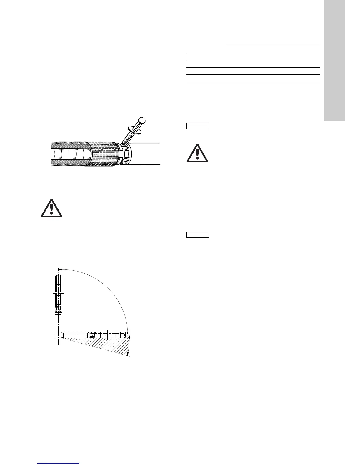
1. Press out the filter in front of the valve at the top of the motor
using a screwdriver. If the filter is slotted, unscrew. Figure 7
shows the position of the filling valve.
2. Press the filling syringe against the valve and inject the liquid.
See fig. 7. If the valve cone is depressed too far, it may be
damaged thus causing the valve to leak.
3. Remove any air in the motor by pressing the point of the filling
syringe lightly against the valve.
4. Repeat the process of injecting liquid and releasing air until
the liquid starts running out or the diaphragm is in its correct
position (Franklin 4" and 6").
5. Refit the filter.
The submersible pump is now ready for installation.
Fig. 7 Position of filling valve
5.2 Positional requirements
Depending on motor type, the pump can be installed either
vertically or horizontally. A complete list of motor types suitable
for horizontal installation is shown in section 5.2.1 Motors suitable
for horizontal installation.
If the pump is installed horizontally, the discharge port should
never fall below the horizontal plane. See fig. 8.
Fig. 8 Positional requirements
If the pump is installed horizontally, e.g. in a tank, we recommend
that you fit it in a flow sleeve.
5.2.1 Motors suitable for horizontal installation
When Franklin 4" motors up to and including 2.2 kW are started
more than 10 times a day, we recommend that you incline the
motor at least 15 ° above the horizontal plane in order to minimise
wearing of the upthrust disc.
5.3 Pump/motor diameter
We recommend that you check the borehole with an inside
calliper to ensure unobstructed passage.
5.4 Liquid temperatures/cooling
The maximum liquid temperature and the minimum flow velocity
past the motor appear from the table below.
We recommend that you install the motor above the well screen
in order to achieve proper motor cooling.
If there is a risk of sediment build-up, such as sand, around the
motor, use a flow sleeve in order to ensure proper cooling of the
motor.
TM00 1354 5092
Warning
If the pump is to be installed in a position where it is
accessible, the coupling must be suitably isolated
from human touch. The pump can for instance be
built into a flow sleeve.
TM00 1355 5092
 Loading...