English (GB)
8
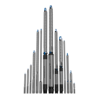
6.3 Lightning protection
The installation can be fitted with a special overvoltage protective
device to protect the motor from voltage surges in the power
supply lines when lightning strikes somewhere in the area.
See fig. 10.
Fig. 10 Fitting an overvoltage protective device
The overvoltage protective device will not, however, protect the
motor against a direct stroke of lightning.
The overvoltage protective device should be connected to the
installation as close as possible to the motor and always in
accordance with local regulations. Ask Grundfos for lightning
protective devices.
MS 402 motors, however, require no further lightning protection
as they are highly insulated.
A special cable termination kit with a built-in overvoltage
protective device is available for Grundfos 4" motors
(product No 799911 or 799912).
6.4 Cable sizing
Make sure that the submersible drop cable can withstand
permanent submersion in the actual liquid and at the actual
temperature.
The cross-section (q) of the cable must meet the following
requirements:
The submersible drop cable must be sized to the rated maximum
current (I
n
) of the motor.
The cross-section must be sufficient to make a voltage drop over
the cable acceptable.
Grundfos supplies submersible drop cables for a wide range of
installations. For correct cable sizing, Grundfos offers a cable
sizing tool on the USB stick supplied with the motor.
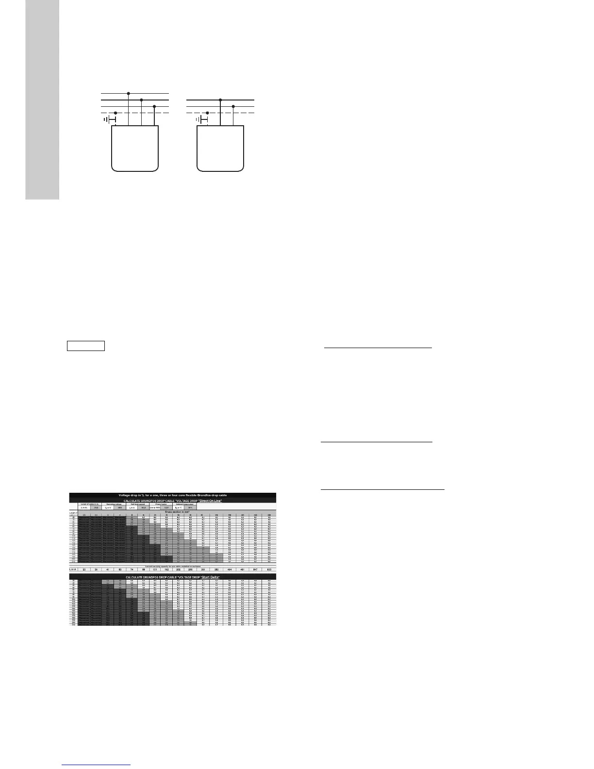
Fig. 11 Cable sizing tool
The sizing tool provides an accurate calculation of the voltage
drop at a given cross-section on the basis of the following
parameters:
• cable length
• operating voltage
• full-load current
• power factor
• ambient temperature.
You can calculate the voltage drop both for direct-on-line and
star-delta starting.
In order to minimise operating losses, the cable cross-section
may be increased. This is only cost-efficient if the borehole
provides the necessary space, and if the operating time of the
pump is long. The cable sizing tool also provides a power loss
calculator that shows the potential savings of an increased
cross-section.
As an alternative to the cable sizing tool, select the cross-section
on the basis of the current values of the given cables.
The cross-section of the submersible drop cable must be large
enough to meet the voltage quality requirements specified in
section 6. Electrical connection.
Determine the voltage drop for the cross-section of the
submersible drop cable by means of the diagrams on pages 17 to
20.
Use the following formula:
I = Rated maximum current of the motor.
For star-delta starting, I = rated maximum current of the motor x
0.58.
Lx = Length of cable converted to a voltage drop of 1 % of the
nominal voltage.
q = Cross-section of submersible drop cable.
Draw a straight line between the actual I-value and the Lx-value.
Where the line intersects the q-axis, select the cross-section that
lies right above the intersection.
The diagrams are made on the basis of the formulas:
Single-phase submersible motor
Three-phase submersible motor
TM00 1357 3605
 Loading...


