English (GB)
13
7.6 Cable clips
Fit cable clips every 3 metres to fix the submersible drop cable
and the straining wire, if fitted, to the riser pipe of the pump.
Grundfos supplies cable clip sets on request.
1. Cut off the rubber band so that the piece with no slit becomes
as long as possible.
2. Insert a button in the first slit.
3. Position the wire alongside the submersible drop cable as
shown in fig. 23.
Fig. 23 Fitting the cable clips
4. Wind the band once around the wire and the cable. Then wind
it tightly at least twice around the pipe, wire and the cable.
5. Push the slit over the button and cut off the band.
Where large cable cross-sections are used, it will be necessary to
wind the band several times.
Where plastic pipes are used, some slackness must be left
between each cable clip as plastic pipes expand when loaded.
When flanged pipes are used, the cable clips should be fitted
above and below each joint.
7.7 Lowering the pump
We recommend that you check the borehole by means of an
inside calliper before lowering the pump to ensure unobstructed
passage.
Lower the pump carefully into the borehole, taking care not to
damage the motor cable and the submersible drop cable.
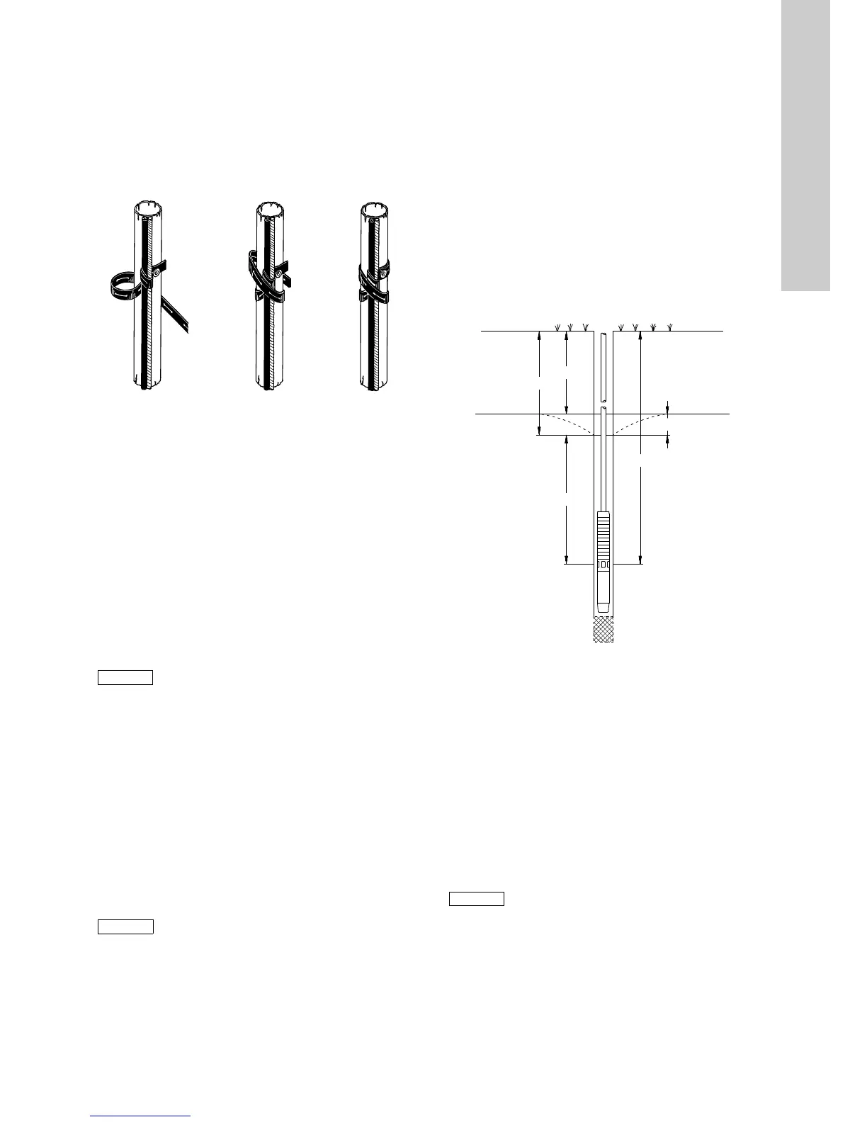
7.8 Installation depth
The dynamic water level should always be above the suction
interconnector of the pump. See section 5.2 Positional
requirements and fig. 24.
Minimum inlet pressure is indicated in the NPSH curve for the
pump. The minimum safety margin should be 1 metre head.
We recommend that you install the pump so that the motor part is
above the well screen in order to ensure optimum cooling.
See section 5.4 Liquid temperatures/cooling.
When the pump has been installed to the required depth, the
installation should be finished by means of a borehole seal.
Slacken the straining wire so that it becomes unloaded and lock it
to the borehole seal by means of wire locks.
8. Startup and operation
8.1 Startup
When the pump has been connected correctly and it is
submerged in the liquid to be pumped, it should be started with
the discharge valve closed off to approximately 1/3 of its
maximum volume of water.
Check the direction of rotation as described in section
6.7.1 Checking the direction of rotation.
If there are impurities in the water, open the valve gradually as
the water becomes clearer. Do not stop the pump until the water
is completely clean, as otherwise the pump parts and the
non-return valve may become blocked.
As the valve is being opened, check the drawdown of the water
level to ensure that the pump always remains submerged.
The dynamic water level should always be above the suction
interconnector of the pump. See section 5.2 Positional
requirements and fig. 24.
Fig. 24 Comparison of various water levels
L1: Minimum installation depth below dynamic water level.
We recommend minimum 1 metre.
L2: Depth to dynamic water level.
L3: Depth to static water level.
L4: Drawdown. This is the difference between the dynamic and
the static water levels.
L5: Installation depth.
If the pump can pump more than yielded by the well, we
recommend that you install the Grundfos MP 204 motor protector
or some other type of dry-running protection.
If no water level electrodes or level switches are installed, the
water level may be drawn down to the suction interconnector of
the pump and the pump will then draw in air.
TM00 1369 5092
 Loading...


