English (GB)
3
4. Applications
Grundfos SP submersible pumps are designed for a wide range
of water supply and liquid transfer applications, such as the
supply of fresh water to private homes or waterworks, water
supply in horticulture and agriculture, drawdown of groundwater
and pressure boosting, and various industrial jobs.
The pump must be installed so that the suction interconnector is
completely submerged in the liquid. The pump can be installed
horizontally or vertically. See section 5.2 Positional requirements.
4.1 Pumped liquids
Clean, thin, non-explosive liquids without solid particles or fibres.
The maximum sand content of the water must not exceed
50 g/m
3
. A larger sand content will reduce the life of the pump
and increase the risk of blockage.
If liquids with a viscosity higher than that of water are to be
pumped, contact Grundfos.
The pump versions SP A N, SP A R, SP N, SP R and SPE are
designed for liquids with higher aggressiveness than drinking
water.
The maximum liquid temperature appears from section 5.4 Liquid
temperatures/cooling.
4.2 Sound pressure level
The sound pressure level has been measured in accordance with
the rules laid down in the EC machinery directive 2006/42/EC.
Sound pressure level of pumps
The values apply to pumps submerged in water, without external
regulating valve.
Sound pressure level of motors
The sound pressure level of Grundfos MS and MMS motors is
lower than 70 dB(A).
Other motor makes: See installation and operating instructions
for these motors.
5. Preparations before installation
5.1 Checking the motor liquid
The motors are factory-filled with a special non-poisonous liquid
which is frost-proof down to -20 °C.
Refill liquid as described below.
5.1.1 Grundfos MS 4000 and MS 402 motors
The filling hole for motor liquid is placed in the following positions:
• MS 4000: in the top of the motor.
• MS 402: in the bottom of the motor.
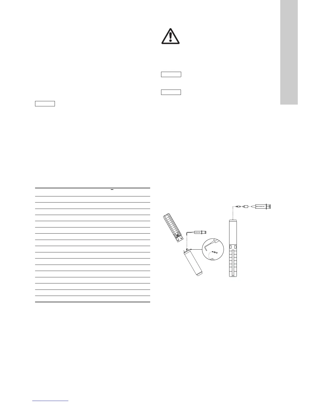
1. Position the submersible pump as shown in fig. 2.
The filling screw must be at the highest point of the motor.
2. Remove the screw from the filling hole.
3. Inject liquid into the motor with the filling syringe until the
liquid runs back out of the filling hole. See fig. 2.
4. Replace the screw in the filling hole and tighten securely
before changing the position of the pump.
Torques
• MS 4000: 3.0 Nm.
• MS 402: 2.0 Nm.
The submersible pump is now ready for installation.
Fig. 2 Motor position during filling - MS 4000 and MS 402
 Loading...


