9 / 19
4.2 Separating and connecting pump and motor
4.2.1 Dismantling
1. Slacken the screw (pos. 18b) and remove it together with the cable guard pos. 18.
2. If the motor is intact, the cable need not be removed. If the motor is defective, remove the Screws (pos.
250) and pull the end cover with cable and socket out of the motor.
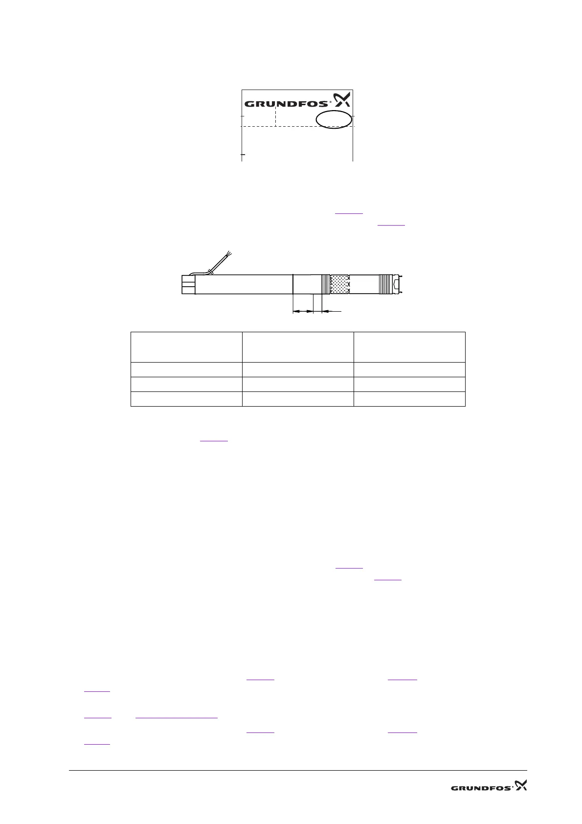
3. Place the motor in a vice, using the two protective clamps pos. B
.
Tighten only on the “A”-marked end of the motor according to table Fig. 3.
.
NOTE: Do not tighten “L”-marked part of the motor due to lack of support.
4. Place a Band pipe wrench pos. E
on the upper pump thread and loosen the pump by max. ½ turn
(right-hand thread). Do not remove the pump from the motor.
5. Slacken the vice. Stand the motor with pump upright with the motor uppermost and tighten the two
clamping faces of the discharge chamber in the vice.
6. Place the band pipe wrench on the pump thread close to the motor and loosen the pump (right-hand
thread).
7. Lift the motor with pump off the vice and place it on a plane surface.
8. Screw the pump off the motor.
4.2.2 Assembly
1. Place the motor in a vice, using the two Protective clamps pos. B
.
Tighten only on the “A”-marked end of the motor according to table Fig. 3.
.
2. Pull the pump shaft a little out of the pump (approx. corresponding to the length of the coupling).
3. Apply a thin layer of grease to the spline inside the coupling and the thread on the motor.
4. Hold the coupling with your fingers and press the coupling home on the motor shaft.
5. Screw the pump home on the motor.
6. Turn motor and pump to a vertical position with the pump upwards and tighten the vice around the
thread below the suction strainer.
7. Using the Key for discharge chamber pos. A
, the Open-end insert tool pos. M and the Torque wrench-
pos. J
tighten the discharge chamber to the sleeve.
8. Turn motor and pump to a horisontal position and place them in a vice, using the two Protective clamps
pos. B
, see Fig. 2.Tighten area.
9. Using the Key for discharge chamber pos. A
, the Open-end insert tool pos. M and the Torque wrench
pos. J
tighten the pump to the motor.
10.Clean and apply a thin layer of grease to the end cover.
TM03 3092 0206
Fig. 2. Tighten area
Motor (P2)
[kW]
A
mm
L
mm
0.70 100 64
1.15 136 82
1.68-1.85 136 46
Fig. 3. Tighten area distance
MSE3NE
PROD.NO.
MODEL B
U: 1 x 200-240 V - 50/60 Hz
P
1: 1.02 kW
P
2
7
kW
I: 5.2 A
96511018
P1 0436
A
L

 Loading...