4
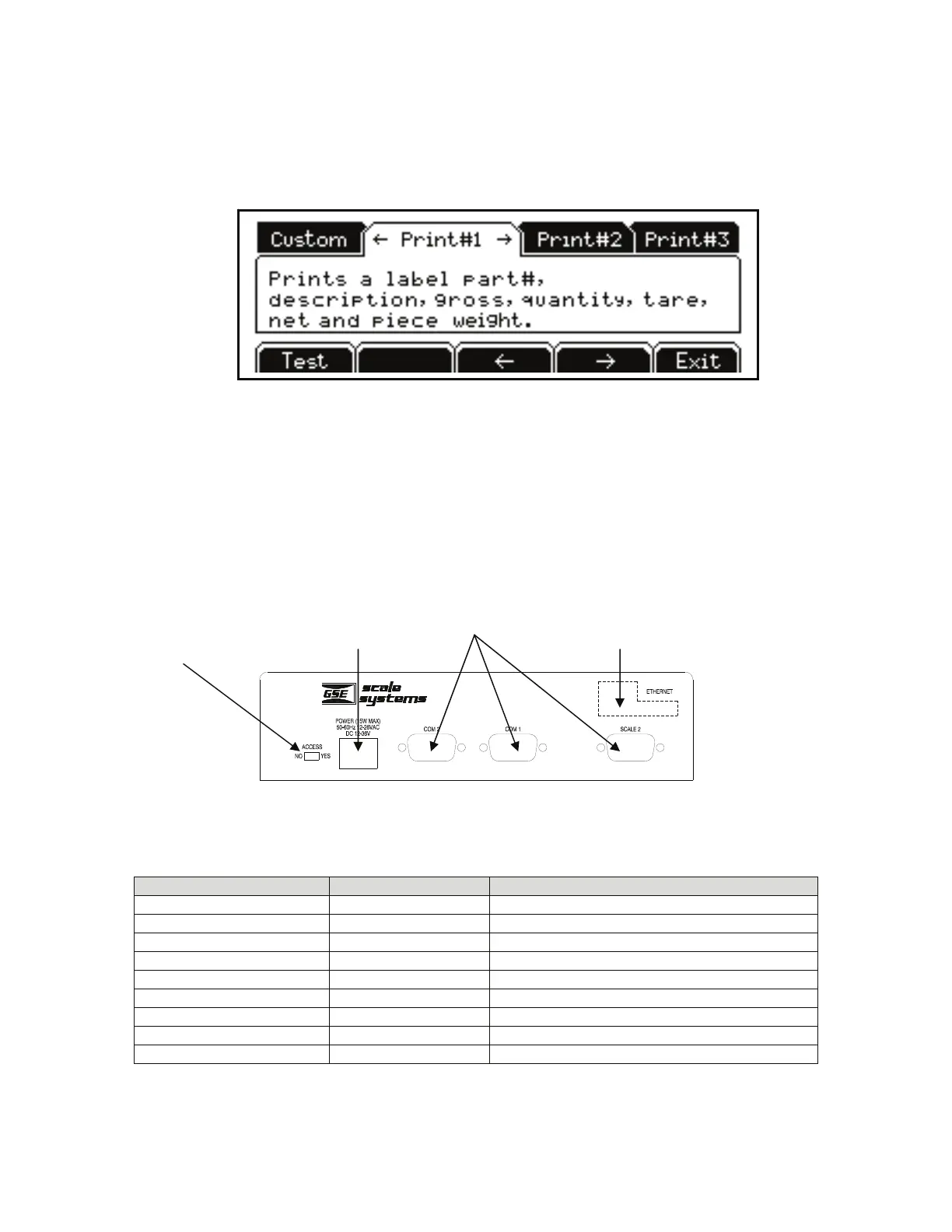
DISPLAY
A graphic 8 line x 40 character LCD provides excellent visibility with user defined help screens and
prompting. The graphic display features a backlight for use in poorly lit areas.
Figure 5: Model 672 Graphic Display
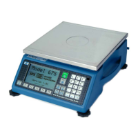
BACK PANEL CONNECTIONS
The Model 672 comes standard with 2 communication ports which use Male DB-9 connectors. Also a
remote base can be connected to the SCALE 2 Female DB-9 connector.
The Ethernet Option Module is optional and is accessible from the rear panel. Simply cut along the dotted
line with a knife where the Ethernet Option Module will be installed. Refer to the Model 675 Technical
Reference Manual for complete details on installing options.
Figure 6: Model 672 Rear Panel
Table 1: Scale 2 DB 9 Connector Pin Out
DB9 pin designation Function Load Cell Cable
1 + Signal 4 or 6 wire
2 - Signal 4 or 6 wire
3 + Sense 4 wire (connect a wire jumper to pin 8)
4 - Sense 4 wire (connect a wire jumper to pin 9)
5 - Excitation 4 or 6 wire
6 + Excitation 4 or 6 wire
7 Chassis Ground 4 or 6 wire
8 + Excitation 4 wire (connect a wire jumper to pin 3)
9 - Excitation 4 wire (connect a wire jumper to pin 4)
Program Switch
672 Precision Scale
Se r i al N o . XXXXXX
Standar
Ethernet Option