Chapter 2: The TopDry™ System
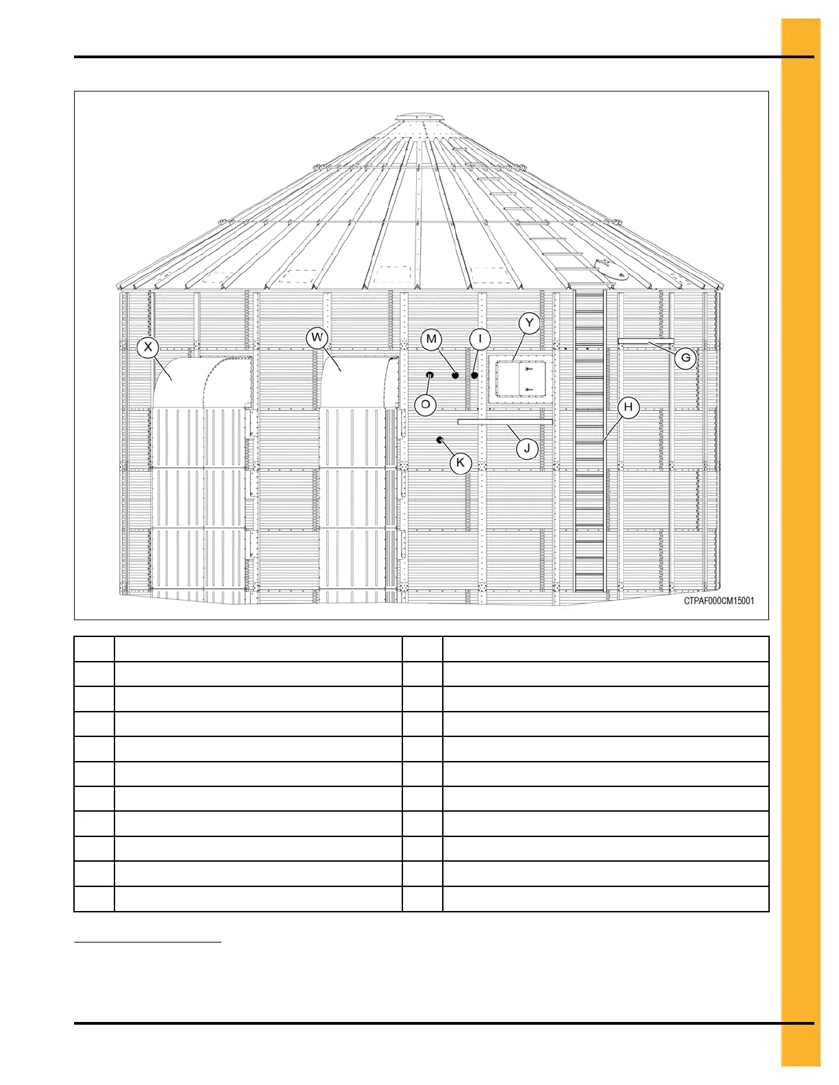
Figure 2-3 Location of TopDry Components and Accessories — Side View
A Fill system no. 2 M
Grain temperature sensor junction box
12
B Fill system no. 1 N
Control fan/heater
C Aeration fan
3
O
Plenum temperature sensor
1
D TopDry drying bin P
Fan/heater (Secondary)
E
Grain temperature sensors Q
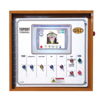
TopDry Terminal control mounted at eye level
F Drying chamber rotary switch R
Cable route
G Eave platform S Chute controller
H Ladder T Fill system control mounted at eye level
I Plenum high limit sensor
12
U
Wet supply rotary switch (optional)
J
Storage chamber platform
V Wet storage bin
K
Storage chamber rotary switch
124
Pneg–4900 TopDry Terminal™ 23
1. Must be in this location between the first two stiffeners to the right of the fan for proper operation.
2. Must be at platform or optional ladder and platform will be required.
3. Must not be placed within 90 degrees of a fan or burner.
4. Must be mounted 3 ft. below heat duct opening
 Loading...