www.gtec-power.de 33
Table 2-9
Trigger EPO when disconnect from J4-2
Trigger EPO when connect to J4-3
Note
J4-1 and J4-2 must be connected in normal operations.
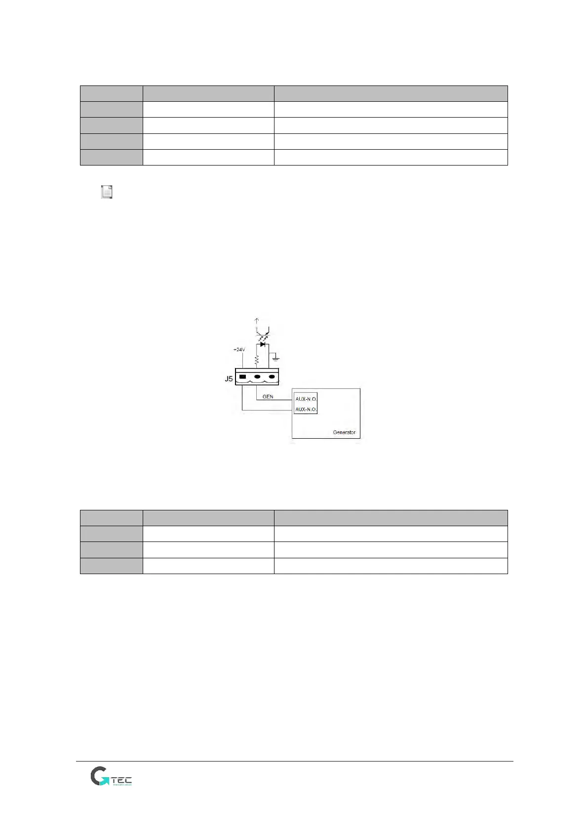
Generator Input Dry Contact
The default function of J5 is the interface for generator input, when connecting J5-2 with +24V
(J5-1), the UPS judges the generator has been connected in the system. The port diagram is
shown in Figure 2-24, the port description is shown in Table 2-10.
Figure 2-24 Diagram of input port for generator input
Table 2-10
Connection status of generator
Battery Circuit Breaker (BCB) Input Port
The default functions of J6 and J7 are the ports for BCB tripping and BCB status, connect J6-1 and
J7-1 to BCB tripper, the port J6-1 can provide a driver signal (+24VDC, 20mA) to trip the battery
breaker when EPO is triggered or EOD (end of discharge) happen. Connect J6-2 and J7-1 to BCB
auxiliary contact NO, connect J7-1 and J7-2 to BCB auxiliary contact trip NO, the UPS would detect
the BCB status, when BCB is closed, it indicates batteries are connected, when open, it alarms
batteries not connected. The port diagram is shown in Figure 2-25, and the description is shown in
Table 2-11.