www.gtec-power.de 29
Attention
After connection restore the protective plastic safety shield before energize the UPS, the electrical
measures to do the activation safety.
Warning
• Tighten the connections terminals to enough torque moment, refer to Table 2-3, and please
ensure correct phase rotation.
• Before connection,ensure the input switch and the power supply are off,attach warnings
label to warn not to operate by others
• The grounding cable and neutral cable must be connected in accordance with local and national
codes.
• When the cable holes does not goes through by cables, it should be filled by the hole stopper.
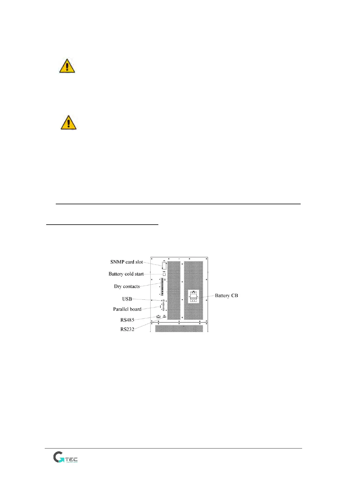
2.7 Control and Communication Cables
UPS is configured with RS232, RS485 interfaces and Drycontact card.
USB and SNMP card are optional, as is shown in Figure 2-8.
Figure 2-8 Dry contact & communication interface
2.7.1 Dry Contact Interface
The UPS provides the dry contact ports from J2 to J10, the input ports J5, J6-2, J7 can be
programmable, the UPS can accept the dry contact signal from these ports to act some
operations. The ports J6-1, J8, J9, and J10 are output port and can be programmable, the UPS
can send out the dry contact signal to external devices for indicating the status of the UPS or
acting. The default definitions of these ports are shown in Table 2-5.