www.gtec-power.de 63
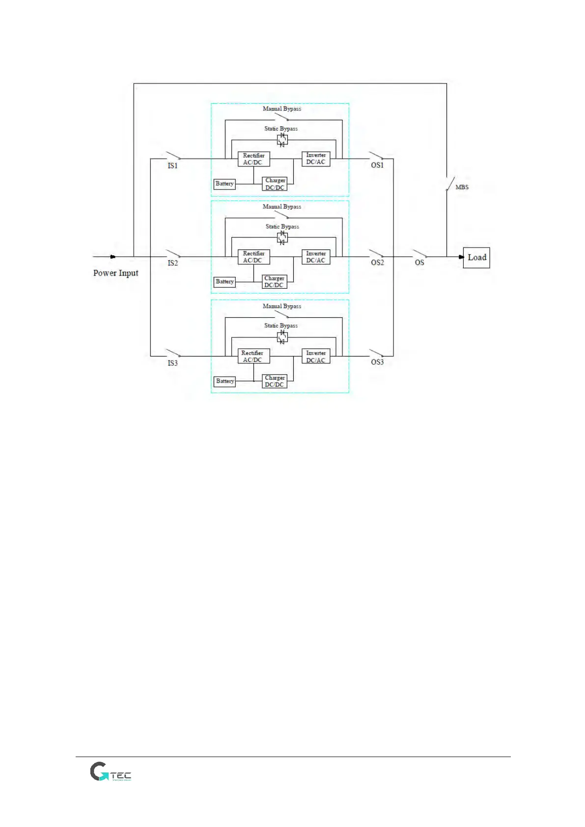
The cable connection drawing for 3UPSs in parallel (common input)
Note: IS1, IS2 and IS3 are the input switches for each UPS, OS1, OS2 and OS3 are the output switches,
OS is the output main switch of the power system, MBS is the maintenance bypass switch.
2. The parallel setting for UPS
Generally users should inform the factory before the order, and the factory will set the parallel
parameters before the delivery. If you need to change from a single system to a parallel system on site,
do as the operations below.
1) Install the parallel board as below
• Remove the parallel interface cover plate and the cover panel on both sides of UPS;
• Fix the parallel board with screws;
• Connect J31 on the parallel board to J31 on the control board with the cable W401;
• Connect J5 on the parallel board to J5 on the control board with the cable W402;
• Connect J8 on the parallel board to J7 on the pin board with the cable W403.
• Reinstall the cover panel of UPS.
Note: Please refer to the below pictures.