18
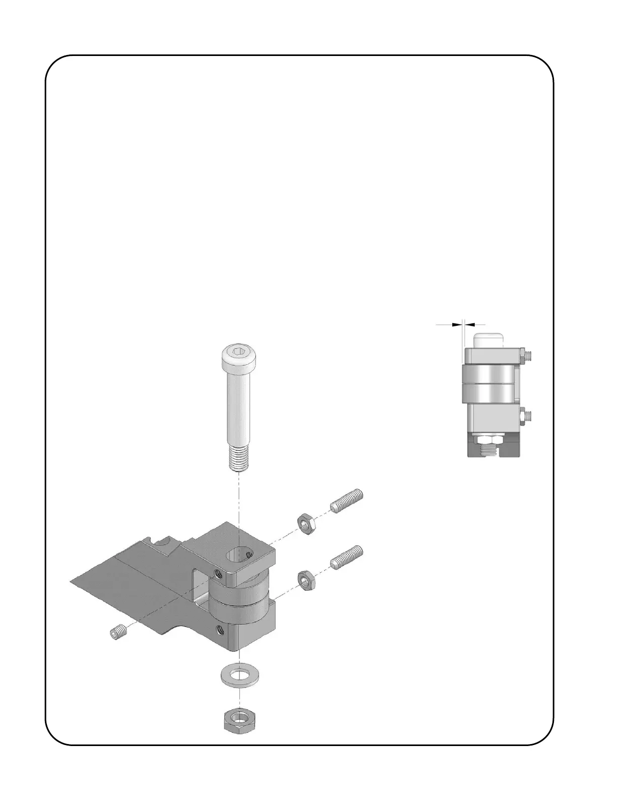
Desirable Setting
for Straight Edge
Plate:
Approximately
0.020” [0.5 mm]
19a) To adjust the Guide Rollers, loosen the guide roller clamp nut (1).
19b) Loosen the 2 set screw jam nuts (2).
19c) Back the lower rear set screw (3) away from the guide roller shoulder bolt (6) so that
the set screw will not interfere with the adjustment of the bolt.
19d) Use the upper rear set screw (4) and the upper front set screw (5) to position and
pinch the guide roller shoulder bolt (6) so that the Guide Rollers are in the desired
position. Both of the upper set screws (4 & 5) should be applying captive pressure to
the guide roller shoulder bolt (6).
19e) Re-tighten the guide roller clamp nut (1).
19f) Screw in the lower set screw (3) so that it rests against the guide roller shoulder bolt
(6) (thus providing extra support against the forces acting on the guide roller
assembly during bevelling operation).
19g) Re-tighten the jam nuts (2).