RM7895A,B,C,D/EC7895A,C; RM7896A,B,C,D 7800 SERIES RELAY MODULES
3 66-1090—3
Wiring Subbase
WARNING
Electrical Shock Hazard.
Can cause serious injury, death or equipment
damage.
Disconnect the power suppl
before be
innin
installation.
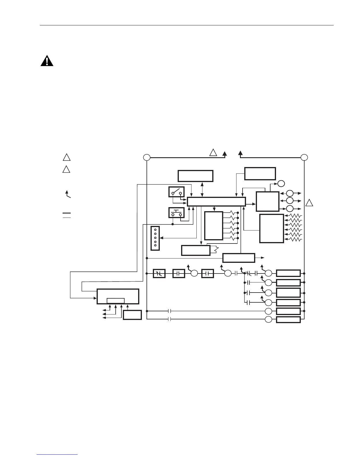
The internal block dia
ram of the RM7895A,B,C,D/
EC7895A,C;RM7896A,B,C,D is shown in Fi
. 1.
1.
For proper subbase wirin
and se
uence chart, refer to
Fi
. 2 and 3.
2.
For remote wirin
of the Ke
board Displa
Module, refer
to the Specifications for the Ke
board Displa
Module
65-0090
, Network Interface Unit
63-2278
, Data
ControlBus Module™
65-0091
or Extension Cable
Assembl
65-0131
.
3.
Disconnect the power suppl
from the main disconnect
before be
innin
installation to prevent electrical shock
and e
uipment dama
e. More than one disconnect can
be re
uired.
4.
All wirin
must compl
with all applicable electrical
codes, ordinances and re
ulations. Wirin
, where
re
uired, must compl
with NEC, Class 1
Line Volta
e
wirin
.
5.
For recommended wire size and t
pe, see Table 1.
6.
For recommended
roundin
practices, see Table 2.
Fig. 1. Internal block diagram of RM7895A,B,C,D/EC7895A,C; RM7896A,B,C,D
(see Fig. 2 and 3 for detailed wiring instructions).
CONFIGURATION
JUMPERS
MICROCOMPUTER
RESET
PUSHBUTTON
RUN/TEST
SWITCH
STATUS LEDs
PLUG-IN PURGE
TIMER CARD
SAFETY RELAY
CIRCUIT
POWER SUPPLY
OPTIONAL KEYBOARD
DISPLAY MODULE
PLUG-IN
FLAME
AMPLIFIER
RELAY
DRIVE
CIRCUIT
CONTROL
POWER
TEST
JACK
REMOTE
RESET
DDL
DDL
COMMUNICATIONS
INDICATES FEEDBACK SENSING
TO RELAY STATUS FEEDBACK
AND LINE VOLT INPUTS
FIELD WIRING
INTERNAL WIRING
IGNITION
PILOT
2ND STAGE
VALVE
MAIN VALVE
1K
RELAY
STATUS
FEEDBACK
AND LINE
VOLTAGE
INPUTS
LIMITS
CONTROLLER
LOCKOUT
INTERLOCK
(INCLUDING
AIRFLOW SWITCH)
1K1 2K1 5K1
FLAME SIGNAL
TEST
PROVIDE DISCONNECT MEANS AND
OVERLOAD PROTECTION AS REQUIRED.
FOR EC7895, MUST USE A 220 TO 240 VAC
TO 120 VAC, 10 VA MINIMUM STEPDOWN
TRANSFORMER (NOT PROVIDED) MUST
BE USED TO DRIVE THE SHUTTER.
RS485
1
2
3
L1
(HOT)
L2
5
6
7
4K1
7K1
2K2
10
8
21
9
7K
6K
5K
4K
3K
2K
F
G
22
1
BLOWER
6K1
4
ALARM
3K1
3
L2
M5110F
1
RM7895, RM7896: 120 VAC, 50/60 HZ.
EC7895A,C: 220-240 VAC, 50/60 HZ.
2
2