RM7895A,B,C,D/EC7895A,C; RM7896A,B,C,D 7800 SERIES RELAY MODULES
66-1090—36
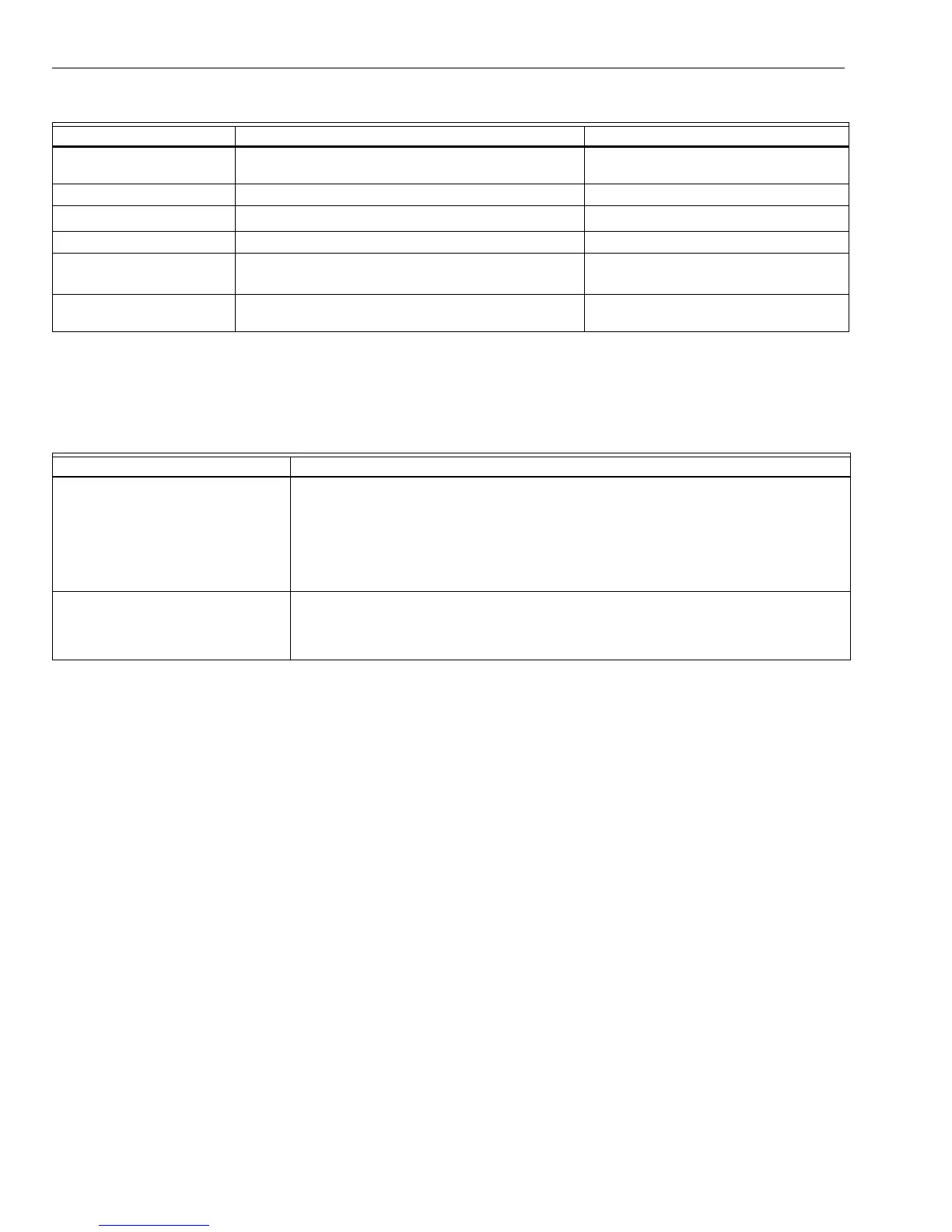
Table 1. Recommended Wire Sizes and Part Numbers.
a
The KDM, Data ControlBus™ Module
for remote mountin
or communications
or Communication Interface ControlBus™
Module must be wired in dais
chain confi
uration, 1
a
-1
a
, 2
b
-2
b
, 3
c
-3
c
. The order of interconnection of all the devices
listed above is not important. Be aware that modules on the closest and farthest end of the dais
chain confi
uration strin
re
uire a 120 ohm
1/4 watt minimum
resistor termination across terminals 1 and 2 of the electrical connectors for connections
over 100 feet
31 meters
.
Table 2. Recommended Grounding Practices.
7.
Recommended wire routin
of leadwires:
a. Do not run hi
h volta
e i
nition transformer wires
in the same conduit with the flame detector, Data
ControlBus Module™, or Remote Reset Module
wirin
.
b. Do not route flame detector, Data ControlBus
Module™, or Remote Reset Module leadwires in
conduit with line volta
e circuits.
c. Enclose flame detector leadwires without armor
cable in metal cable or conduit.
d. Follow directions in flame detector, Data ControlBus
Module™, or Remote Reset Module Instructions.
8.
The KDM is powered from a low volta
e, ener
limited
source. It can be mounted outside of a control panel if it
is protected from mechanical dama
e.
NOTE: A 13 Vdc power suppl
must be used an
time more
than one KDM is used.
9.
Maximum wire len
ths:
a. RM7895A,B,C,D/EC7895A,C; RM7896A,B,C,D
leadwires: The maximum leadwire len
th is 300 feet
to terminal inputs
Control, Runnin
/Lockout
Interlock
.
b. Flame Detector leadwires: The maximum flame
sensor leadwire len
th is limited b
the flame si
nal
stren
th.
c. Remote Reset leadwires: The maximum len
th of
wire is 1000 feet
305 meters
to a Remote Reset
pushbutton.
d. Data ControlBus Module™: The maximum Data
ControlBus Module™ cable len
th depends on the
number of s
stem modules connected, the noise
conditions and the cable used. The maximum len
th
of all Data ControlBus Module™ interconnectin
wire is 4000 feet
1219 meters
.
10.
Be sure loads do not exceed the terminal ratin
s. Refer
to the label on the RM7895A,B,C,D/EC7895A,C;
RM7896A,B,C,D or to the terminal ratin
s in Table 3.
Final Wiring Check
1.
Check the power suppl
circuit. The volta
e and
fre
uenc
tolerance must match those of the
RM7895A,B,C,D/EC7895A,C; RM7896A,B,C,D. A
separate power suppl
circuit can be re
uired for the
RM7895A,B,C,D/EC7895A,C; RM7896A,B,C,D. Add
the re
uired disconnect means and overload protection.
2.
Check all wirin
circuits and complete Static Checkout
in Table 4 before installin
the RM7895A,B,C,D/
EC7895A,C; RM7896A,B,C,D on the subbase.
3.
Install all electrical connectors.
4.
Restore power to the panel.
Application Recommended Wire Size Recommended Part Numbers
Line volta
e terminals. 14, 16 or 18 AWG copper conductor, 600 volt insulation,
moisture-resistant wire.
TTW60C, THW75C, THHN90C.
Ke
board Displa
Module 22 AWG two-wire twisted pair with
round, or five-wire. Belden 8723 shielded cable or e
uivalent.
Data ControlBus™ Module
a
22 AWG two-wire twisted pair with
round, or five-wire. Belden 8723 shielded cable or e
uivalent.
Remote Reset Module 22 AWG two-wire twisted pair, insulated for low volta
e. —
Communications Interface
ControlBus™ Module
a
22 AWG two-wire twisted pair with
round. Belden 8723 shielded cable or e
uivalent.
13 Vdc full-wave rectified
transformer power input.
18 AWG wire insulated for volta
es and temperatures
for
iven application.
TTW60C, THW75C, THHN90C.
Ground Type Recommended Practice
Earth
round
subbase and rela
module
.
1. Use to provide a connection between the subbase and the control panel of the
e
uipment. Earth
round must be capable of conductin
enou
h current to blow the
20A fuse
or breaker
in the event of an internal short circuit.
2. Use wide straps or brackets to provide minimum len
th, maximum surface area
round conductors. If a leadwire is re
uired, use 14 AWG copper wire.
3. Make sure that mechanicall
ti
htened
oints alon
the
round path are free of
nonconductive coatin
s and protected a
ainst corrosionon matin
surfaces.
Si
nal
round
Ke
board Displa
Module, Data ControlBus™ Module,
Communications Interface
ControlBus™ Module.
Use the shield of the si
nal wire to
round the device to the si
nal
round terminal 3
c
of
each device. Connect the shield at both ends of the dais
chain to earth
round.