RM7895A,B,C,D/EC7895A,C; RM7896A,B,C,D 7800 SERIES RELAY MODULES
66-1090—310
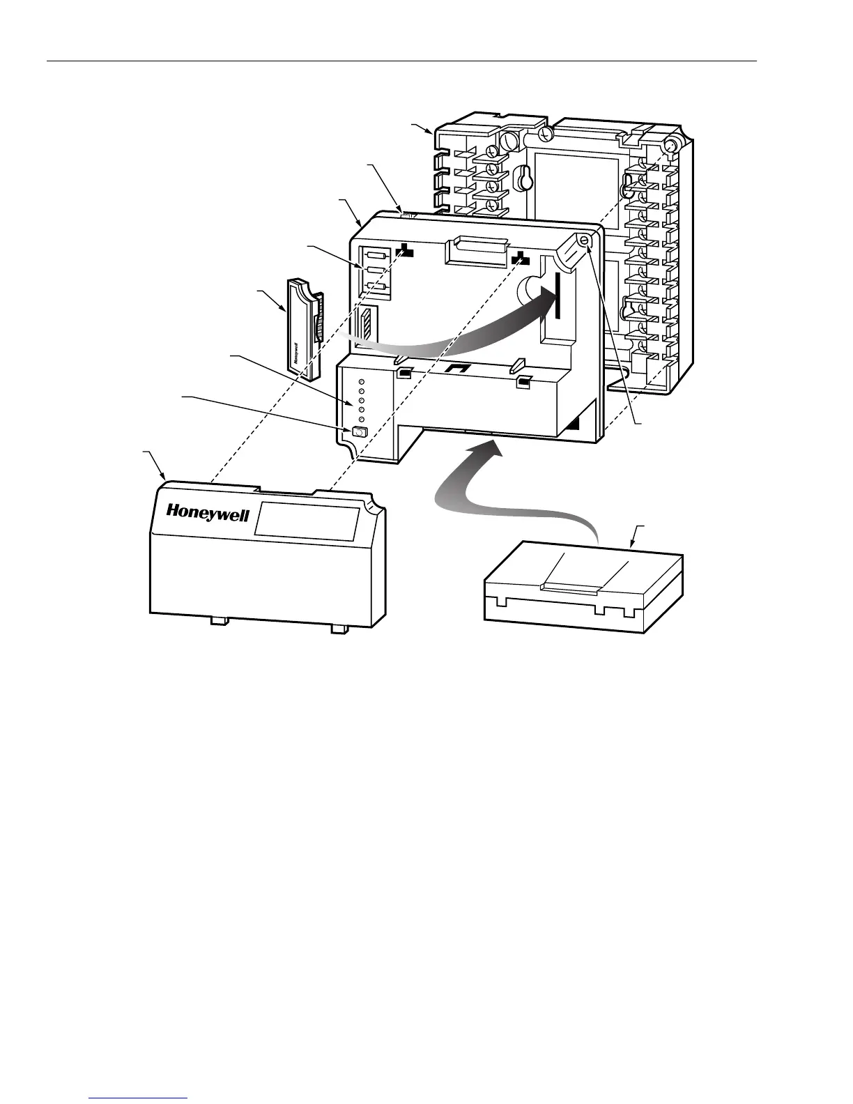
Fig. 4. RM7895A,B,C,D/EC7895A,C; RM7896A,B,C,D Relay Module, exploded view.
2.
STANDBY PERIOD
a. Airflow lockout feature is enabled and the airflow
switch does not close after ten seconds or within the
specified pur
e card timin
.
b. Flame si
nal is detected after 30 seconds.
c. I
nition/pilot valve/intermittent pilot valve terminal is
ener
ized.
d. Main valve terminal is ener
ized.
e. Dela
ed main valve terminal is ener
ized
RM7895C,D
.
f. Internal s
stem fault occurred.
.Pur
e card is removed.
h. Pur
e card is bad.
3.
PREPURGE PERIOD
a. Airflow lockout feature is enabled and the airflow
switch opens.
b. I
nition/pilot valve terminal is ener
ized.
c. Main valve terminal is ener
ized.
d. Dela
ed main valve terminal is ener
ized
RM7895C,D
.
e. Internal s
stem fault occurred.
f. Pur
e card is removed.
.Pur
e card is bad.
h. Flame si
nal is detected.
4.
PILOT FLAME ESTABLISHING PERIOD
PFEP
a. Airflow lockout feature is enabled and the airflow
switch opens.
b. No flame si
nal at end of PFEP.
c. I
nition/pilot valve/intermittent pilot valve terminal is
not ener
ized.
NOTE: For the RM7895C1020 and RM7896C1036, durin
the first 8 seconds of PFEP, when a flame si
nal is
detected, terminal 10 is de-ener
ized. If the flame
si
nal is lost, terminal 10 will re-ener
ize.
d. Main valve terminal is ener
ized.
e. Dela
ed
second sta
e
main valve terminal is
ener
ized
RM7895C,D/EC7895C; RM7896C,D
.
f. Internal s
stem fault occurred.
.Pur
e card is removed.
h. Pur
e card is bad.
HONEYW
ELL
POWER
PILOT
FLAME
MAIN
ALARM
RESET
DUST
COVER
PURGE
TIMER
WIRING
SUBBASE
CAPTIVE
MOUNTING
SCREW
RUN/TEST (C,D ONLY)
SWITCH
CONFIGURATION
JUMPERS
RELAY
MODULE
SEQUENCE
STATUS
LED PANEL
RESET
BUTTON
FLAME
AMPLIFIER
BURNER CONTROL
M15122
 Loading...