66-1090—3 G.R. Rev. 1-01 www.hone
well.com
RM7895A,B,C,D/EC7895A,C; RM7896A,B,C,D 7800 SERIES RELAY MODULES
Home and Building Control Home and Building Control
Honeywell Honeywell Limited-Honeywell Limitée
1985 Douglas Drive North 35 Dynamic Drive
Golden Valley, MN 55422 Scarborough, Ontario
M1V 4Z9
Printed in U.S.A. on recycled
paper containing at least 10%
post-consumer paper fibers.
Run
1.
The EC7895C, RM7895C,D, RM7896C,D has a
dela
ed main valve that is ener
ized once the RUN
period is entered.
2.
The rela
module is now in RUN and remains in RUN
until the controller input, terminal 6, opens, indicatin
that the demand is satisfied or a limit has opened.
Post Purge (RM7896A,B,C,D Only)
After demand is satisfied or a limit opens, de-ener
izin
terminal 6, the I
nition/Pilot valve, main valve and dela
ed
main valve, terminals 8, 9 and 21, are de-ener
ized. The
blower motor, terminal 4, remains powered for 15 seconds.
Run/Test Switch (RM/EC7895C,D; RM7896C,D only)
The Run/Test Switch is located on the top side of the rela
module, see Fi
. 5. The Run/Test Switch allows the burner
se
uence to be altered as follows:
1.
In the measured PREPURGE se
uence, the Run/Test
Switch, placed in the TEST position, causes the
PREPURGE timin
to stop.
2.
In the Pilot Flame Establishin
Period, the Run/Test
Switch, placed in the TEST position, stops the timer
durin
the first ei
ht seconds of a ten-second PFEP
selection or durin
the first three seconds of a
four-second PFEP selection. It also allows for pilot
turn-down test and other burner ad
ustments. This
activates a fifteen-second flameout timer that permits
pilot flame ad
ustment without nuisance safet
shutdowns. The Run/Test Switch is i
nored durin
PFEP for the C and D rela
modules if terminals
8 and 9 or 9 and 21 are
umpered.
IMPORTANT
When the relay module is switched to the TEST
mode, it stops and holds at the next Run/Test Switch
point in the operating sequence. Make sure that the
Run/Test Switch is in the RUN position before
leaving the installation.
Fig. 5. Sequence Status LEDs.
SETTINGS AND ADJUSTMENTS
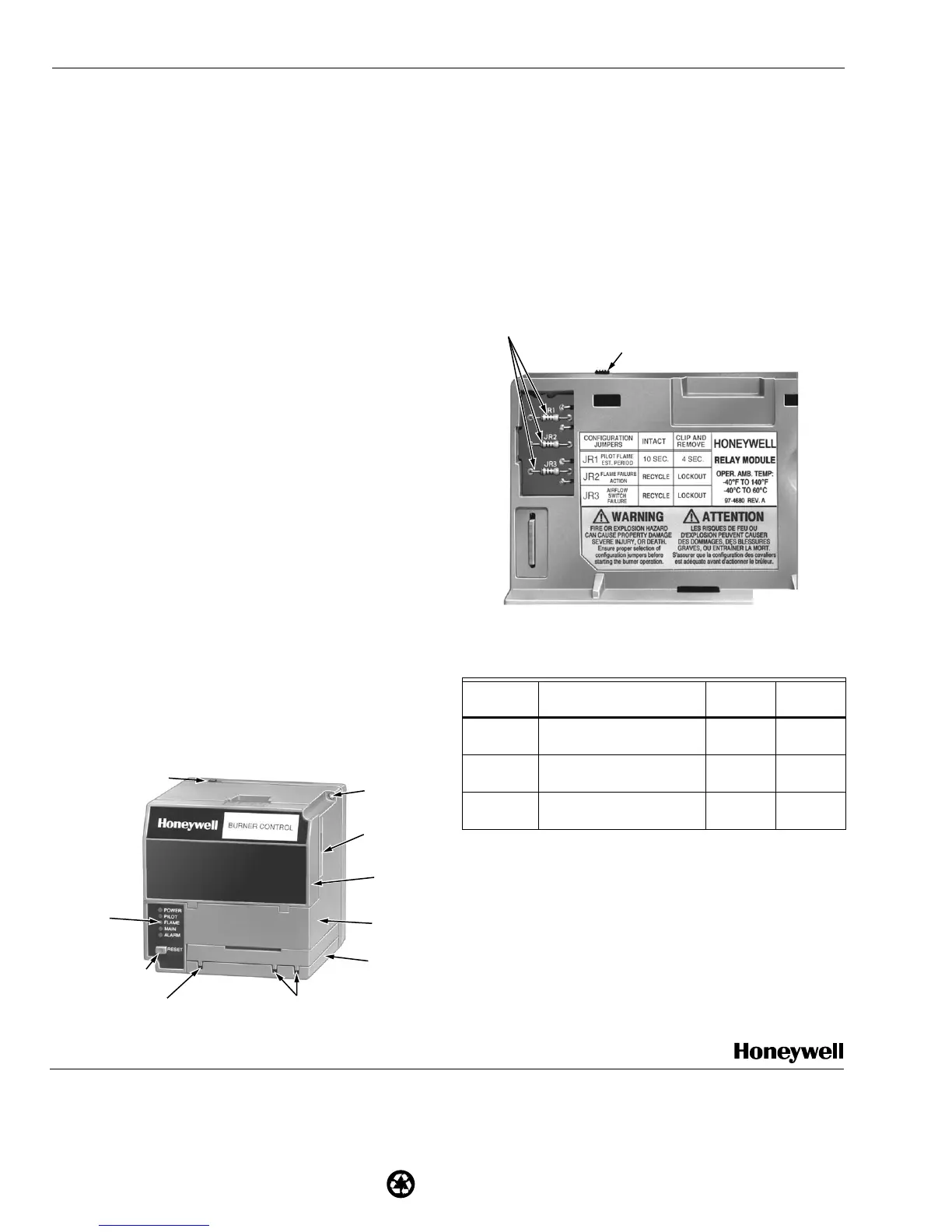
Selectable Site-Configurable Jumpers
The rela
module has three site-confi
urable
umper options,
see Fi
. 6 and Table 6. If necessar
, clip the site-confi
urable
umpers with side cutters and remove the resistors from the
rela
module.
SERVICE NOTE:
Clippin
and removin
a site-confi
urable
umper enhances the level of safet
.
Fig. 6. Selectable site-configurable jumpers.
Table 7. Site-configurable jumper options.
a
The RM7895C1020 and RM7896C1036 have fixed PFEP of
ten seconds and do not have
umper JR1.
IMPORTANT
Clipping and removing a jumper after 200 hours of
operation causes a nonresettable Fault 110. The
relay module must then be replaced.
SEQUENCE
STATUS
LEDs
RESET
PUSHBUTTON
FLAME
SIMULATOR INPUT
FLAME CURRENT
TEST JACKS
RUN/TEST SWITCH
(RM7895C,D;
EC7895C;
RM7896C,D)
CAPTIVE
MOUNTING
SCREW
PLUG-IN
PURGE
CARD
DUST
COVER
RELAY
MODULE
FLAME
AMPLIFIER
M7552A
Jumper
Number Description Intact Clipped
JR1
a
Pilot Flame Establishin
Period
PFEP
10
seconds
4 seconds
JR2 Flame Failure Action
Rec
cle
Lockout
JR3 Airflow Switch
ILK
Failure
Rec
cle Lockout
RUN/TEST SWITCH
(EC7895C; RM7895C,D; RM7896C,D)
SELECTABLE CONFIGURATION JUMPERS
M7553A
 Loading...