Bulletin 700-HR
General Purpose Relays and Timing Relays
9-98
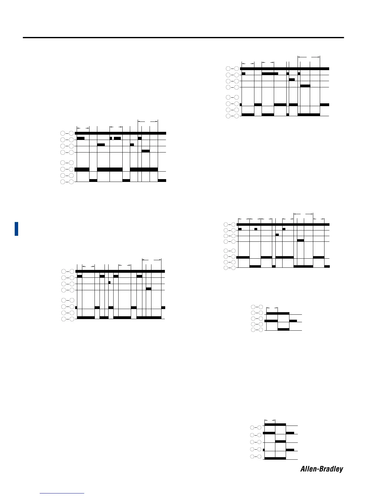
Timing Charts
Bulletin 700-HR, -HRC, and -HRM Dial Timing Relay (T = Time Range 0.05 s…60 h)
Bulletin 700-HR
On-Delay (PO): Input power must be applied continuously. When a start
signal is applied the timing cycle begins. The output con tacts change
state after the time delay is completed. The contacts will return to their
shelf state when a reset signal is applied or power is removed.
• The start signal can be either momentary or maintained.
• Reapplying a start signal during the timing cycle will have no effect
onthetimedelay.
• The start signal can be eliminated by jumpering terminals ➁ and ➅.
The timing cycle will now begin upon application of power to
terminals ➁ and ➉.
Off-Delay (SF): Input power must be applied continuously. When a start
signal is applied the output contacts change state immediately. When
the start signal is removed the timing cycle begins. The output contacts
will return to their shelf state once the time delay is completed. Reset
will occur when a reset signal is applied or power is removed.
• The start signal must be maintained until the timing cycle is to begin.
• If the start signal is reapplied after the timing cycle has begun, the
time delay resets and will not begin again until the start signal is
removed.
ATTENTION: If the start signal is a maintained signal the timer will initiate
a new off delay immediately upon removal of the reset signal.
One Shot (OS): Input power must be applied continuously. When a start
signal is applied the output contacts change state immediately and the
timing cycle begins. The output contacts return to their shelf state once
the time delay is completed. Reset will occur when a reset signal is
applied or power is removed.
• The start signal can be either momentary or maintained.
• Reapplying a start signal during the timing cycle will have no effect
onthetimedelay.
• Reapplying a start signal after the time delay is completed will start a
new timing cycle (no reset is required).
• The start signal can be eliminated by jumpering terminals ➁ and ➅.
The time delay w ill now begin when power is applied to terminals ➁
and ➉, similar to an “interval on” timing mode.
Repeat Cycle (FL): Input power must be applied continuous ly. When a
start signal is applied the “off timing cycle” begins, but the output contacts
remain in the shelf state. When the time delay is completed the output
contacts change state and the next “on timing cycle” begins. When this
time delay is completed the output contacts return to their shelf state.
This sequence will repeat until a reset signal is applied or power is
removed.
• The start signal can be either momentary or maintained.
• Reapplying a start signal during the timing cycle will have no effect
onthetimedelay.
• The start signal can be eliminated by jumpering terminals ➁ and ➅.
The time delay w ill now begin when power is applied to terminals ➁
and ➉.
• This is a symm etrical timing relay where the “off cycle” and “on cycle”
are of equal value.
Bulletin 700-HRM
On-Delay: When power is applied to terminals ➁ and ➆ the timing cycle
begins. The output contacts change state after the time delay is
completed. The contacts will return to their shelf state when power is
removed.
Bulletin 700-HRC
On-Delay: When power is applied to terminals ➁ and ➆ th
e
ins
tantaneous output contacts (IC) change state and the timing cycle
begins. The timed output contacts (T C) change state after the time delay
is completed. All contacts will return to their shelf state when power is
removed.
(T) is the set time delay.
(t) is a timing cycle less than the set time delay. (t) can reflect that a reset
signal has been applied or power has been removed prior to completion
of the time delay. (t) can also indicate that prior to completion of the time
delay a gate signal has been applied which momentarily interrupts the
timing cycle.
(T-t) is the completion of the time delay after the gate signal is removed
(X) is the duration of the gate signal.
102
2 6
2 7
2 5
11
9
31
118
1 4
{
{
NC
NO
{
TC
S
R
G
T
T
tXT
_
t
T
t
T
T
_
tXt T
T
G
R
S
TC
{
NO
NC
{
{
41
8 11
1 3
9 11
5
2
72
62
2 10
t
T
T
_
tXtT
T
G
R
S
TC
{
NO
NC
{
{
41
8 11
1 3
9 11
5
2
72
62
2 10
T TT t
T
T
_
tXtTT
G
R
S
TC
{
NO
NC
{
{
41
8 11
1 3
9 11
5
2
72
62
2 10
{
{
NC
NO
{
TC
72
T
68
31
58
1 4
TC
NC
{
NO
NO
{
NC
IC
72
T
31
41
68
8 5
 Loading...