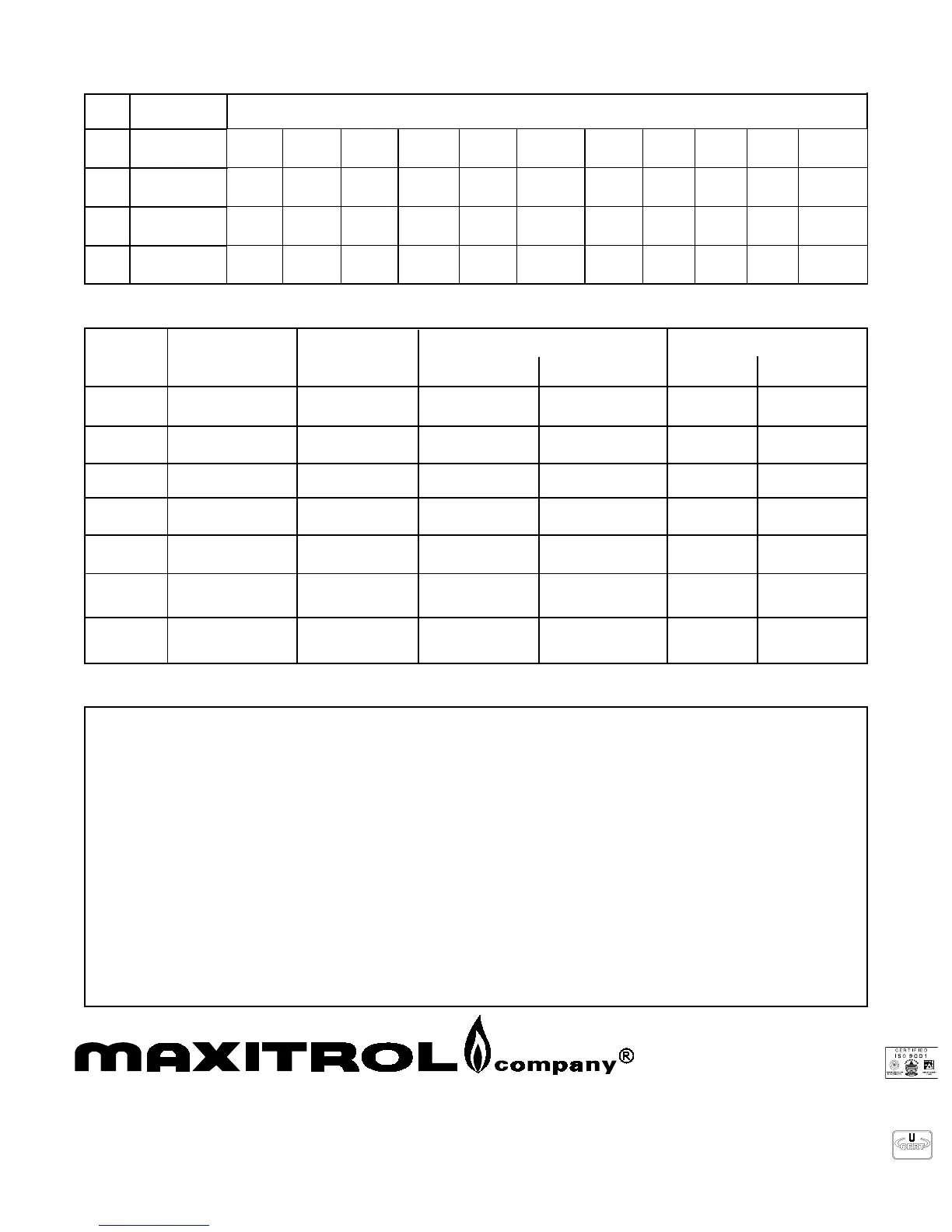
SPRING SELECTION CHART — inches water column (millibars)
2.8” to 5.2”
(6.9 to 13)
5.3-0.1
)8.8-5.2(
_________0.8-0.4
)02-01(
_________01-0.6
)52-51(
21-0.8
)03-02(
___
5.3-0.1
)8.8-5.2(
_________0.8-0.4
)02-01(
_________01-0.6
)52-51(
21-0.8
)03-02(
21-9
)03-5.22(
5.3-0.1
)8.8-5.2(
______3.4-8.3
)8.01-5.9(
0.8-0.4
)02-01(
3.5-7.4
)3.31-8.11(
___4.6-6.5
)61-41(
01-0.6
)52-51(
21-0.8
)03-02(
3.11-7.9
)3.82-2.42(
5.3-0.1
)8.8-5.2(
_________0.8-0.4
)02-01(
___21-0.5
)03-5.21(
___01-0.6
)52-51(
______
RV12
RV20
CV47
RV47
RV48
2.8” to 5.2”
(6.9 to 13)
2.8” to 5.2”
(6.9 to 13)
3.0” to 6.0”
(7.5 to 15)
Model
Standard
Spring
Other Springs Available
www.maxitrol.com
European Representatives
Industriestrasse 1 48308 Senden, Germany
49.2597.9632.0 • Fax 49.2597.9632.99
Warnstedter Strasse 3 06502 Thale, Germany
49.3947.400.0 • Fax 49.3947.400.200
A copyrighted publication of
Maxitrol Company
23555 Telegraph Rd., P.O. Box 2230
Southfield, MI 48037-2230 U.S.A.
248.356.1400 • Fax 248.356.0829
DIN EN ISO 9001
86
CAPACITY CHART — expressed in Btu/h (cubic meters/h) — 0.64 sp gr gas
Model Pipe Size
Pressure Drop
@ 0.3” w.c.
or (.7mb)
Range of Regulations
Main Burner
M.B. and Pilot
Individual Load
Fixed Orifice
Ball Check
Devices
RV12
1/8” x 1/8”*
3/16”Lox x 3/16”Lox
RV20
RV20C
CV47
RV47
CV47A & C
RV47A & C
RV48
RV48C
1/4” x 1/4”
3/8” x 3/8”*
1/4” x 1/4”
3/8” x 3/8”
3/8” x 3/8”
1/2 x 1/2”*
3/8” x 3/8”
1/2” x 1/2”
1/2” x 1/2”
3/4” x 3/4”
1/2” x 1/2”
3/4” x 3/4”
14,800 (.42)
8,800 (.25)
30,000 (.85)
30,000 (.85)
55,000 (1.5)
60,000 (1.7)
55,000 (1.5)
60,000 (1.7)
130,000 (3.7)
150,000 (4.2)
130,000 (3.7)
150,000 (4.2)
30,000 (.85)
65,000 (1.84)
75,000 (2.11)
125,000 (3.5)
125,000 (3.5)
230,000 (6.5)
250,000 (7.1)
400,000 (11.3)
25,000 (.71)
15,000 (.43)
50,000 (1.4)
50,000 (1.4)
90,000 (2.5)
125,000 (3.5)
230,000 (6.5)
250,000 (7.1)
275,000 Nat (7.0)
250,000 LP (2.8)
20,000 (.56)
15,000 (.43)
30,000 (.85)
15,000 (.42)
40,000 (1.1)
40,000 (1.1)
40,000 (1.1)
40,000 (1.1)
—
—
—
90,000 (2.5)
125,000 (3.5)
160,000 (4.5)
160,000 (4.5)
NOTE: Minimum main burner regulation capacity for all models (except “N”) is 150 Btu/h (.0042 m
3
/h).
* Available as loxit connection.
HOW TO CALCULATE PRESSURE DROP AT VARIOUS FLOW RATES FROM CAPACITY CHART:
FORMULA: P2 = P1 x (Q2/Q1)
2
Q1 = Known flow rate at 0.3” w.c. (see chart).
SELECTING A REGULATOR WITH SUFFICIENT CAPACITY:
A. Check Capacity Chart insuring regulator has ample range
of regulation and individual load capacities (for use with
pilot) for the application.
B. Know minimum encountered inlet pressure.
MINIMUM INLET PRESSURE MINUS “P2” MUST BE
GREATER THAN DESIRED OUTLET PRESSURE.
Solve for “P2 using above formula.
EXAMPLE: 1/2”NPT regulator required for main burner
and pilot.
Desired maximum flow rate = 150,000 Btu/h.
Maximum individual load = 150,000 Btu/h.
Minimum inlet pressure = 7.0” w.c.
Required outlet pressure = 5.0” w.c.
Using the Capacity Chart shows the RV48 is the only regulator
satisfying the requirements in “A”.
P2 = 0.3” w.c. x (150,000/130,000)
2
= 0.4” w.c.
7.0” w.c. — 0.4” w.c. = 6.6” w.c.
6.6” w.c. is greater than the required Po of 5.0” w.c.
THE RV48 (non “L” fixed orifice), VENTED OR W/12A04
BALL CHECK DEVICE, IS THE CORRECT REGULATOR
FOR THIS APPLICATION.
P2 = Pressure drop at desired flow rate. Q2 = Desired flow rate.
P1 = Known pressure drop (in this case 0.3” w.c.).
 Loading...