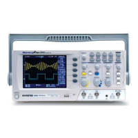
6. Connect the probe between the Channel1 input
terminal and probe compensation signal output
(2Vp-p, 1kHz square wave).
7. Set the probe attenuation voltage to x10.
VOLTS/DIV VOLTS/DIV TIME/DIV
CH 1 MATH CH 2 MENU MENU
Acquire
Display
Utility Help
Run/Stop
VARIABLE
FORCE
Autoset
Cursor
SINGLE
Hardcopy
Measure
Save/Recall
LEVEL
VERTICAL HORIZONTAL TRIGGER
CH1
CAT300V
M
W
15pF
MAX. 300Vpk
1
CH2 EXT TRIG
CAT300V
M
W
15pF
MAX. 300Vpk
1
X Y
8. Press the Autoset key. A
square waveform will
appear in the center of the
display. For details on
Autoset, see page 47.
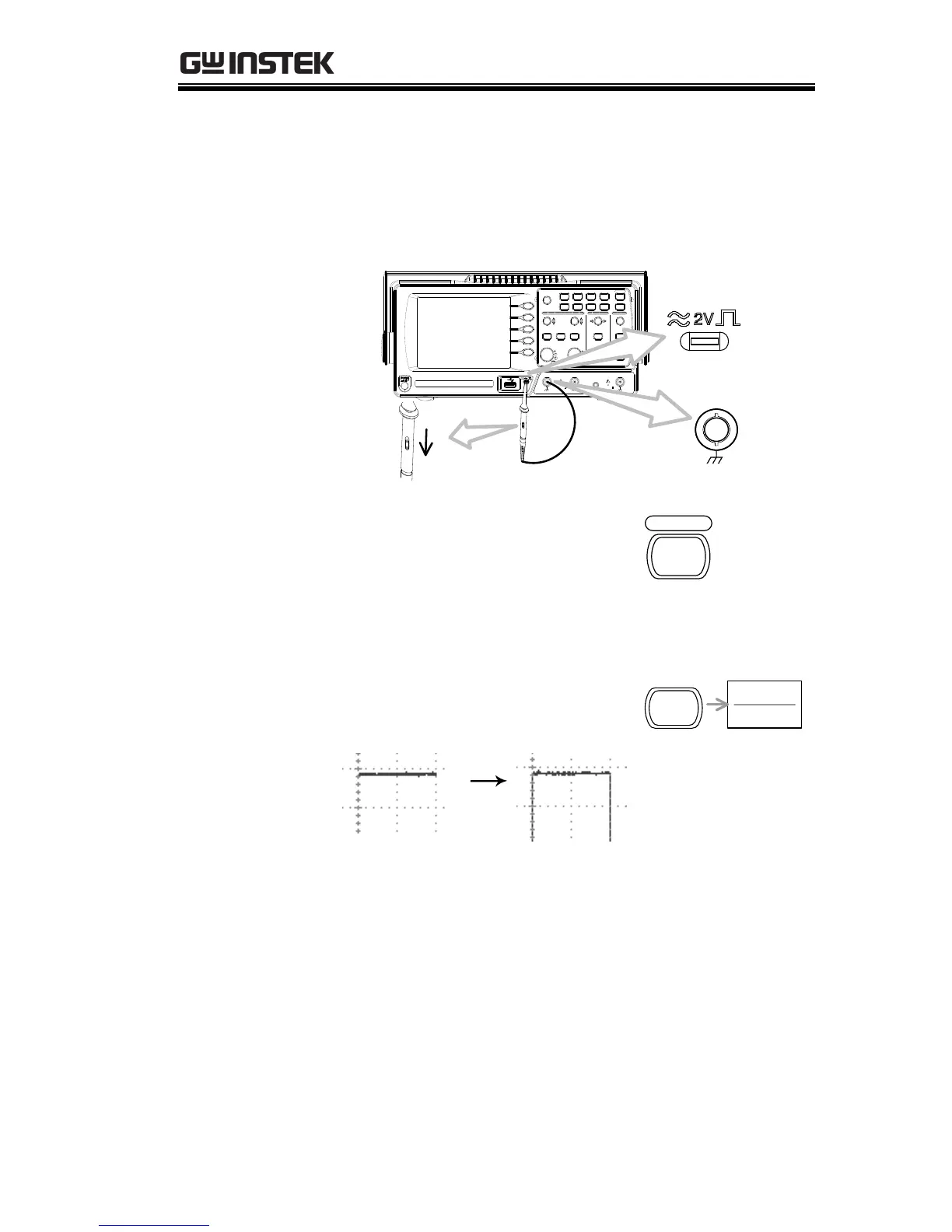
9. Press the Display key, then
Type and select the vector
waveform type.
10. Turn the adjustment point on the probe to
flatten the square waveform edge.
 Loading...