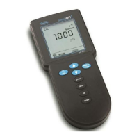
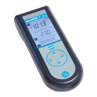
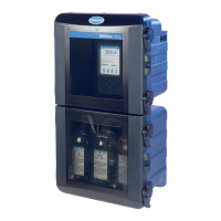
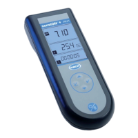
Figure 4 Measurement screen (top part)
1 Date and time 7 Primary measurement value (user-selected
parameter)
2 Battery status 8 Stability icon with warning icon and warning
message
3 USB (COM port) active connection icon when
communication class is selected
9 Probe icon, port number, parameter or probe name
4 Progress bar (not completed measurement) 10 Slot number, parameter name and chemical
symbol
5 Calibration status icon (calibration not correct) 11 Very important message for devices (followed by
error and then warning message)
6 Secondary measurement (user-selected parameter)
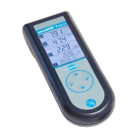
Figure 5 Measurement screen (lower part)
1 Probe icon, port number, parameter or probe name 8 Active arrow keys
2 Calibration status icon (calibration correct) 9 Site ID icon and site name
3 Secondary measurement value (user-selected
parameter)
10 Routes icon (shows when routes is set to on)
4 Tertiary measurement value (user-selected
parameter)
11 Options (contextual: Details, exit, cancel, select,
deselect)
5 Right and left arrows to select the applicable site ID 12 Primary measurement value (user selected)
6 Options (contextual: Read, select, OK, delete) 13 Stability icon
7 Checkmark: Completed measurement on site
5.2 Keypad description
Refer to Figure 6 for the keypad description and navigation information.
English
9

 Loading...
